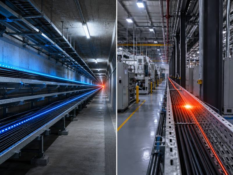
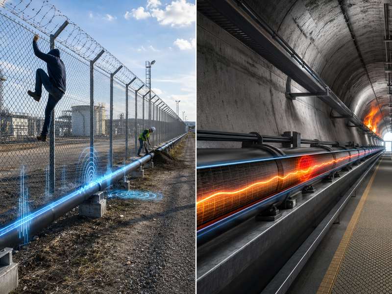
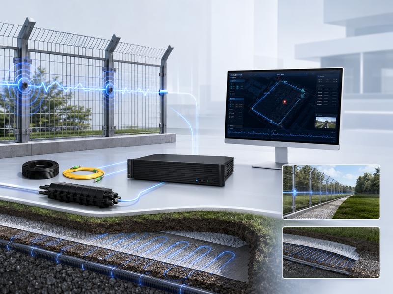
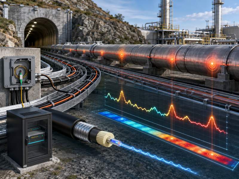
Fibre optic cables are used in Distributed Temperature Sensing (DTS), which continually measures temperature across great distances. It is widely used for fire detection, power cables, pipelines, tunnels, oil and gas sites, data centers, industrial plants, storage tanks, and environmental monitoring.
DTS is powerful, but real projects may face inaccurate readings, poor calibration, weak signals, fiber damage, false alarms, slow response, data overload, and integration issues.
Inaccurate Temperature Measurement
Temperature accuracy is one of the most important performance factors in a DTS system. If the measured temperature is wrong, the system may fail to detect overheating, fire risk, pipeline leakage, or abnormal thermal conditions.
Inaccurate readings can occur when the system is not calibrated correctly, when the reference temperature is unstable, or when fiber attenuation is not properly compensated. Calibration is especially important because DTS temperature estimation depends on signal interpretation, not only on direct sensor contact.
Common Causes of Inaccurate Readings
| Cause | Explanation | Result |
| Poor calibration | Reference points are not accurate | Wrong temperature profile |
| Fiber attenuation | The signal becomes weaker with distance | Temperature error in the far sections |
| Connector loss | Dirty or damaged connectors reduce the signal | Sudden abnormal readings |
| Wrong cable type | Cable not suitable for the environment | Poor heat transfer or unstable data |
| Environmental interference | Moisture, strain, vibration, or external heat | Measurement deviation |
How to Solve It
The first solution is proper calibration. Use known temperature reference points, such as ice bath, water bath, calibrated temperature sensors, or stable reference sections. Research on DTS calibration shows that carefully designed calibration methods can significantly improve measurement accuracy compared with relying only on raw instrument-calibrated data.
Second, check fiber loss and attenuation. Long fiber routes naturally reduce signal strength, and this may affect temperature resolution. Silixa notes that temperature resolution in DTS is limited by signal attenuation and signal-to-noise ratio, and averaging multiple measurements can improve resolution.
Third, avoid using one calibration setting for all conditions. For demanding applications, calibration should be reviewed after installation, after maintenance, and after major environmental changes.
Weak Signal and Poor Signal-to-Noise Ratio
A weak optical signal can reduce DTS accuracy, response stability, and measurement reliability. This problem is common in long-distance systems, old fiber cables, poor splices, damaged connectors, or installations with high optical loss.
When the signal-to-noise ratio is poor, the DTS system may show unstable temperature curves, random fluctuations, or reduced accuracy at the far end of the cable.
Symptoms of Weak Signal
- Temperature data becomes noisy at long distances
- Far-end measurement is less stable
- Some zones show sudden spikes or drops
- The system requires a long averaging time
- Alarm accuracy becomes unreliable
- The optical loss test shows abnormal attenuation
How to Solve It
Before commissioning, perform optical testing. OTDR testing can help locate high-loss points, fiber breaks, sharp bends, poor splices, and connector problems. Clean all connectors and check that fiber ends are properly protected.
If the route is too long, consider using a higher-performance DTS unit, better fiber cable, lower-loss splicing, or a double-ended measurement configuration. Double-ended DTS can improve accuracy because the system measures from both directions and compensates for differential attenuation more effectively.
Also, avoid unnecessary connectors and patch points. Every connector or splice may introduce loss. For long-distance monitoring, a clean and continuous fiber route is always better.
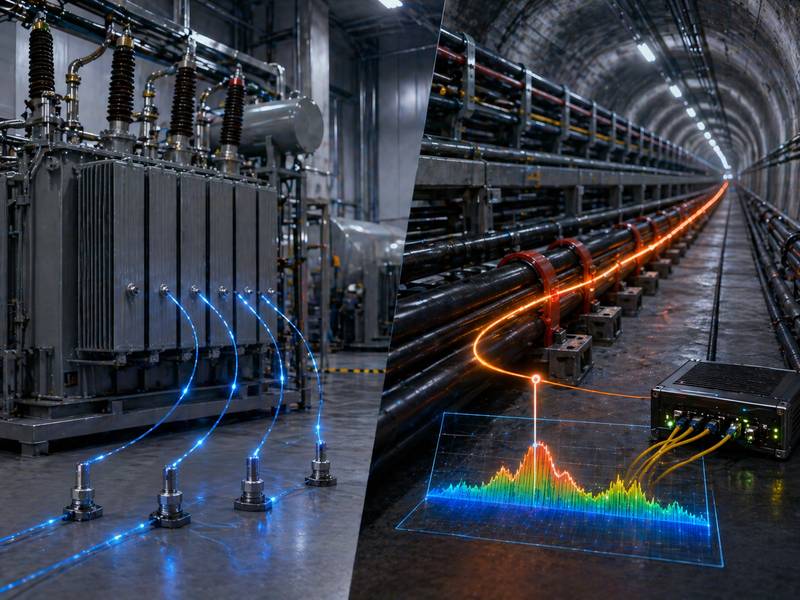
Poor Cable Installation
The sensing component of a DTS system is the fibre optic cable. If the cable is poorly installed, the system cannot accurately reflect the true temperature of the monitored object or environment.
For example, if a DTS cable is used for power cable monitoring but is not placed close enough to the power cable, the measured temperature may be lower than the actual hotspot. If a fire detection cable is installed too far from the ceiling or hazard area, detection may be delayed.
Common Installation Problems
| Installation Problem | Possible Impact |
| Cable not in contact with the target surface | Delayed or inaccurate temperature reading |
| Cable too far from the heat source | Missed hotspot or slow alarm |
| Sharp bends | Optical loss or cable damage |
| Poor mechanical protection | Fiber break or signal loss |
| Inconsistent installation route | Uneven temperature response |
| Cable exposed to physical damage | Long-term reliability problem |
How to Solve It
Before installation, define the monitoring objective clearly. A DTS cable used for tunnel fire detection, power cable monitoring, pipeline leakage detection, or tank temperature monitoring may require different installation methods.
For direct temperature monitoring, the cable should have good thermal contact with the target surface. For environmental monitoring, the cable should be placed where it can represent the actual temperature field. For buried or embedded applications, installation depth, soil condition, and cable protection must be carefully controlled.
Use proper fixing accessories, protective conduits, cable trays, clamps, or armored cable according to the site environment. Avoid sharp bending and follow the cable manufacturer’s minimum bending radius.
Slow Temperature Response
Some users expect DTS to detect temperature changes instantly. However, response time depends on cable structure, installation method, thermal contact, sampling interval, and averaging settings.
A heavily armored cable may provide strong protection, but it may respond more slowly to rapid temperature changes. A cable installed inside a conduit may be protected from damage, but the conduit may delay heat transfer. A long averaging time can improve measurement stability, but it may also slow alarm response.
Factors That Affect Response Time
| Factor | Effect |
| Cable jacket material | Influences the heat transfer speed |
| Armored cable structure | Improves protection but may slow response |
| Installation method | Direct contact is faster than indirect contact |
| Sampling interval | Affects data update frequency |
| Averaging time | Improves stability but may delay detection |
| Distance from heat source | A greater distance means a slower response |
How to Solve It
Choose the cable according to the application. For fire detection, faster thermal response may be more important. For underground pipeline or power cable monitoring, mechanical protection and long-term durability may be equally important.
Balance response speed and data stability. If alarm response is too slow, reduce averaging time or optimize alarm logic. If the data is too noisy, increase averaging or improve cable installation quality.
For critical alarm zones, place the cable closer to the heat source and use appropriate alarm thresholds.
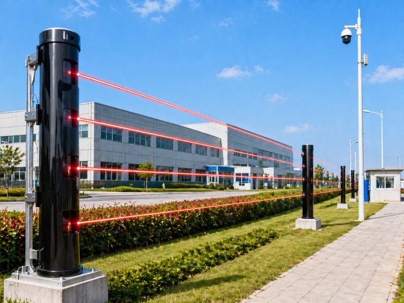
False Alarms
False alarms are a common problem in DTS-based fire detection and thermal monitoring systems. A false alarm may be triggered by sunlight, temporary heat sources, hot machinery, steam, nearby vehicles, welding work, or poor alarm threshold settings.
Operators may lose faith in the system if false alerts occur too frequently. In high-security or high-risk facilities, repeated false alarms can also increase labor cost and reduce response efficiency.
Common False Alarm Sources
- Direct sunlight on the exposed cable
- Hot exhaust air from equipment
- Steam release or hot water cleaning
- Welding and maintenance activity
- Poorly selected alarm thresholds
- Wrong zone configuration
- Unstable reference temperature
- Sudden environmental changes
How to Solve It
Use zone-based alarm settings. A cable section near hot equipment should not use the same alarm threshold as a normal corridor or tunnel section. Divide the fiber route into meaningful alarm zones based on site conditions.
Use multiple alarm criteria, not only absolute temperature. For example, many DTS applications use temperature rise rate, maximum temperature, temperature difference, or thermal trend analysis. This helps distinguish a real fire or overheating event from normal environmental variation.
For outdoor applications, consider sunlight exposure, seasonal changes, and local climate. Alarm settings should be tested during real operation, not only during indoor commissioning.
Missed Alarms or Delayed Alarms
The opposite of false alarms is missed alarms. This is more dangerous because the system may fail to warn operators about overheating, fire, leakage, or equipment failure.
Missed alarms may happen when the cable is too far from the heat source, sensitivity is too low, alarm thresholds are too high, or averaging time is too long.
Causes of Missed or Delayed Alarms
| Cause | Example | Solution |
| Cable too far away | Cable not close to power cable hotspot | Improve cable route |
| Threshold too high | Fire or overheating not detected early | Adjust alarm values |
| Long averaging time | Alarm response becomes slow | Reduce averaging for critical zones |
| Wrong zone setting | High-risk area treated as low-risk | Redesign alarm zones |
| Cable inside thick conduit | Heat transfer is delayed | Use better installation method |
How to Solve It
Perform real event simulation during commissioning. For fire detection, use controlled heat tests according to safety rules. For power cable monitoring, simulate thermal load if possible. For pipeline applications, test whether the cable can detect expected thermal changes.
Review alarm records and trend data. If abnormal temperature changes are visible in data but no alarm is triggered, the alarm logic needs adjustment.
Fiber Damage and Cable Failure
Fiber optic cables are strong but not indestructible. They can be damaged by construction work, crushing, rodents, water ingress, corrosion, bending, pulling force, or poor protection.
A damaged fiber may cause signal loss, missing sections, unstable readings, or total system failure.
Common Cable Damage Risks
- Excavation or digging damage
- Rodent bite
- Mechanical impact
- Water ingress
- Cable crushing
- Chemical corrosion
- Excessive pulling tension
- Sharp bending
- Poor splice protection
How to Solve It
Use the correct cable type for the environment. For underground installation, armored and moisture-resistant cable may be necessary. For industrial plants, chemical resistance, high-temperature resistance, and mechanical protection should be considered. For tunnels or buildings, flame-retardant cable may be required.
Protect splices and junction boxes. Many failures happen not in the middle of the cable, but at connection points, termination boxes, or poorly sealed enclosures.
Keep accurate cable route drawings. If future construction teams do not know where the fiber is located, accidental damage becomes more likely.
Poor Spatial Resolution
Spatial resolution means how precisely the DTS system can identify the location and size of a temperature event. Poor spatial resolution may cause small hotspots to be blurred or difficult to locate.
This is important for power cable joints, battery storage systems, tunnels, conveyors, pipelines, and equipment rooms where a small hotspot may indicate a serious problem.
Why Spatial Resolution Becomes Poor
- System setting is not suitable
- The cable route is too long
- The signal-to-noise ratio is low
- Averaging settings are too high
- Hotspot is smaller than the resolution capability
- The fiber cable is not close enough to the heat source
How to Solve It
Select a DTS system with suitable spatial resolution for the application. Do not choose only by monitoring distance. A system that can monitor very long distances may not always provide the best resolution for small hotspot detection.
For small critical assets, place the cable closer to the heat source or use a denser cable layout. In some cases, a looped cable layout around critical equipment can improve detection coverage.
Data Overload and Difficult Interpretation
DTS systems can generate large amounts of temperature data along long fiber routes. For example, a single system may monitor thousands of measurement points. Yokogawa explains that DTS can provide thousands of temperature measurements over long distances using the optical fiber itself as the sensing element.
Without proper data management, operators may struggle to understand alarms, trends, reports, and historical records.
Data Management Problems
| Problem | Impact |
| Too many measurement points | Difficult to identify key areas |
| Poor zone naming | Operators cannot locate alarms quickly |
| No trend analysis | Early warning opportunities are missed |
| Too many alarms | Alarm fatigue |
| No integration | Data remains isolated from control systems |
How to Solve It
Use clear zone naming. Instead of “Channel 1, Section 5,” use practical names such as “Cable Tunnel Zone A,” “Transformer Area,” “Tank Farm North Line,” or “Pipeline Valve Station 2.”
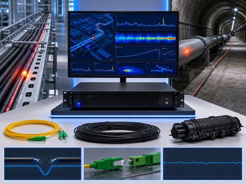
Use dashboards and trend reports. A good DTS platform should help operators see maximum temperature, temperature rise rate, alarm location, historical trend, and zone status.
Integrate DTS with SCADA, fire alarm systems, building management systems, or security platforms when needed. Integration helps convert temperature data into useful operational decisions.
Poor Integration with Existing Systems
DTS is often part of a larger monitoring or safety system. It may need to connect with fire alarm panels, SCADA systems, VMS platforms, emergency systems, power management systems, or industrial control platforms.
When communication protocols, alarm formats, zone definitions, or control logic are not aligned, integration issues may arise.
Common Integration Requirements
- Relay output
- Modbus TCP
- OPC UA
- Ethernet communication
- Fire alarm panel connection
- SCADA integration
- Alarm notification system
- Data logging platform
- Remote monitoring platform
How to Solve It
Confirm integration requirements before purchasing the DTS system. The project team should define alarm outputs, communication protocols, data format, control room display, and response workflow in advance.
Test integration before final handover. It is not enough for the DTS system to show an alarm on its own software. The alarm must also reach the platform where operators actually work.
Lack of Maintenance
DTS systems are often installed in harsh environments and expected to operate continuously. Without maintenance, small problems can become serious failures.
DTS Maintenance Checklist
- Check optical power and signal quality
- Inspect connectors and clean if needed
- Review alarm history and false alarm zones
- Check the fiber route after construction work
- Inspect junction boxes and splice closures
- Verify reference temperature points
- Test alarm output and platform integration
- Update system software if required
- Recalibrate after major site changes
- Backup configuration and historical data
How to Solve It
Create a scheduled maintenance plan. For critical safety applications, regular inspection is essential. Maintenance should also be performed after storms, construction activity, equipment relocation, or cable repair.
Summary Table: Common DTS Problems and Solutions
| Problem | Main Cause | Practical Solution |
| Inaccurate temperature | Poor calibration, attenuation | Use reference calibration and attenuation compensation |
| Weak signal | Fiber loss, dirty connectors | Clean connectors and perform OTDR testing |
| False alarms | Wrong threshold, local heat sources | Use zone-based alarm logic |
| Missed alarms | Cable too far from the heat source | Improve cable placement and sensitivity |
| Slow response | Cable structure or averaging time | Optimize cable type and system settings |
| Cable failure | Mechanical damage or water ingress | Use a protected cable and inspect the route |
| Poor spatial resolution | Wrong system selection or layout | Choose a suitable resolution and cable design |
| Data overload | Too many points without structure | Use zone naming, dashboards, and reports |
| Integration failure | Protocol or workflow mismatch | Confirm integration requirements early |
| Long-term drift | Lack of maintenance | Recalibrate and inspect regularly |
Best Practices for Reliable DTS Projects
To build a reliable DTS system, project teams should follow these best practices:
- Define the monitoring purpose before system design.
- Choose the right DTS cable for the environment.
- Plan the cable route carefully.
- Avoid sharp bends and high-loss splices.
- Use proper calibration reference points.
- Divide the fiber route into logical alarm zones.
- Adjust alarm thresholds based on actual site conditions.
- Test the system with simulated temperature events.
- Integrate alarms with the user’s main monitoring platform.
- Create a long-term inspection and maintenance plan.
Distributed Temperature Sensing (DTS) provides continuous long-distance temperature monitoring for fire detection, power cables, pipelines, tunnels, industrial sites, and critical infrastructure.
Reliable DTS performance depends on proper calibration, suitable cable selection, correct installation, good thermal contact, accurate alarm settings, optical testing, and regular maintenance.
With the right design and operation, DTS delivers accurate temperature monitoring, early warning, and long-term safety protection.