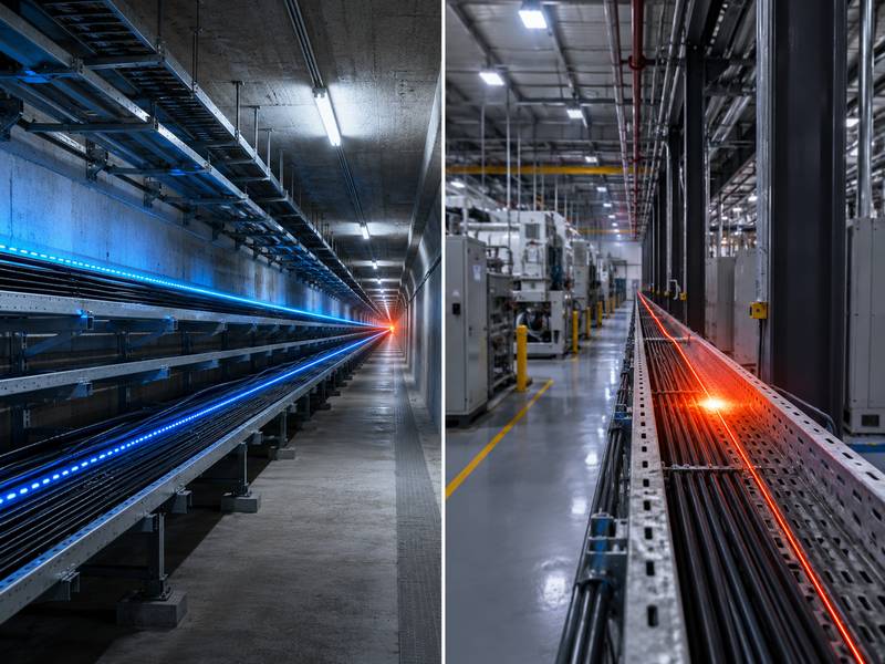
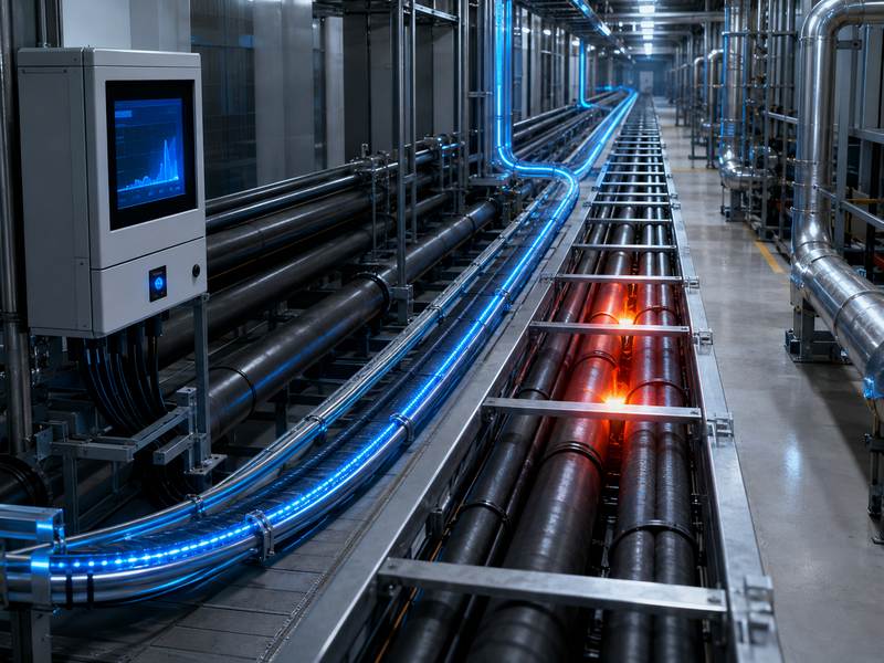
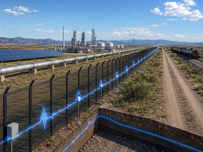
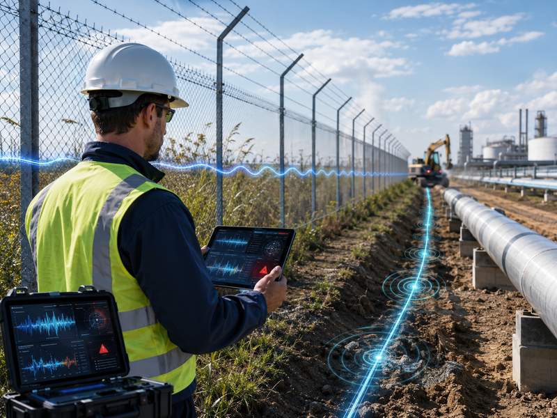
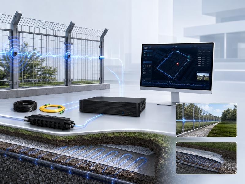
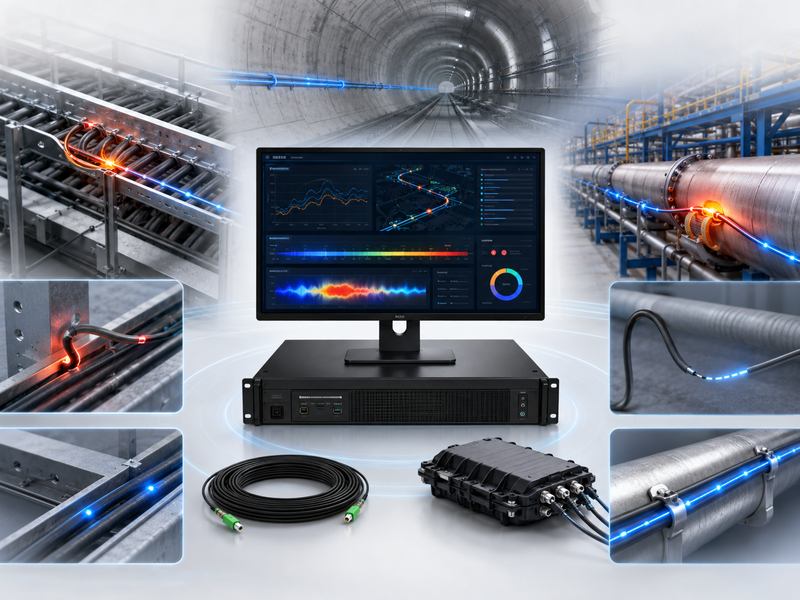
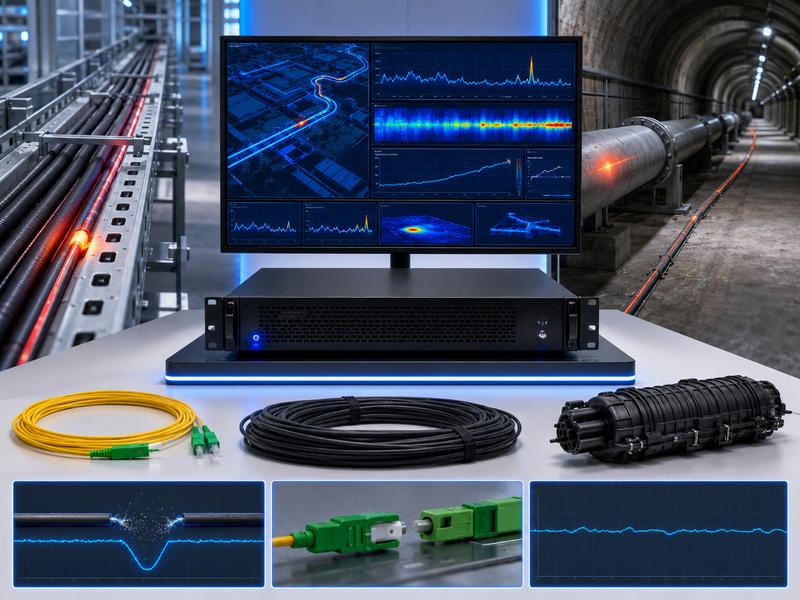
Distributed Temperature Sensing (DTS) monitors temperature over long distances in cable corridors, pipelines, tunnels, tanks, plants, mines, and fire detection systems.
It helps detect overheating, fire risks, cable faults, leakage, and abnormal temperature changes early. Common problems often come from poor installation, wrong settings, unsuitable cables, weak splicing, dirty connectors, interference, or incomplete calibration.
This guide covers common DTS problems, causes, and solutions.
Quick Overview of Common DTS Problems
| Problem | Common Cause | Main Solution |
| No temperature signal | Fiber break, wrong connection, device fault | Check fiber continuity, ports, and host status |
| Weak signal | High optical loss, poor splicing, dirty connector | Clean connectors, test loss, redo fusion splicing |
| Inaccurate temperature | Wrong calibration or cable mismatch | Recalibrate and set correct fiber parameters |
| False alarms | Bad threshold settings or environmental influence | Adjust alarm logic and set zone-based thresholds |
| Missed alarms | Threshold too high or poor cable contact | Improve cable layout and lower alarm threshold |
| Short sensing distance | Excessive fiber loss or wrong cable type | Use suitable fiber and control total link loss |
| Unstable data | Power, network, or grounding issues | Check power supply, communication, and grounding |
| Difficult fault location | Poor map configuration | Match fiber distance with physical route |
No Temperature Signal
One of the most common distributed temperature sensing problems is no temperature signal on the monitoring platform. The system may show no data, no fiber trace, or only a flat abnormal line. This usually means the DTS host cannot receive a valid optical signal from the sensing fiber.
Possible causes include a broken optical fiber, disconnected jumper, wrong port connection, dirty connector, excessive bending, incorrect channel selection, or device startup failure. In some cases, the fiber is connected to the wrong channel, so the software displays no valid temperature data for the selected route.
To solve this problem, first check the DTS host status, power supply, and channel configuration. Then inspect the optical jumper and sensing fiber connection. Make sure the connector type matches the DTS port, such as FC/APC or other project-specific interface types. If the connector is not properly oriented, do not push it into the port.
Next, use an optical time-domain reflectometer or optical power meter to check fiber continuity and link loss. If a fiber break is found, locate the break point, repair the cable, and protect the splice properly. After repair, restart the channel scan and confirm whether the temperature trace returns to normal.
Weak Optical Signal
A weak optical signal can reduce measurement quality and shorten the available sensing distance. The DTS system may still show temperature data, but the signal curve may be noisy, unstable, or incomplete at long distances.
Common causes include poor fusion splicing, contaminated connectors, high connector insertion loss, damaged fiber, cable bending, old fiber, or excessive total route length. In long-distance DTS applications, small loss at each splice point can accumulate and affect the whole system.
The solution is to control optical loss from the beginning of the project. Clean all optical connectors before connection. Use proper fusion splicing tools and test every splice point. Avoid sharp bending, pulling, crushing, or twisting of the sensing cable. For outdoor and industrial environments, use splice boxes with waterproof and dustproof protection.
| Optical Signal Issue | Possible Cause | Recommended Action |
| Signal drops suddenly | Fiber break or damaged splice | Locate fault and repair fiber |
| Signal gradually weakens | Long distance or high total loss | Check design distance and optical budget |
| Signal fluctuates | Loose connector or poor contact | Reconnect and clean connector |
| High loss after splice | Poor fusion quality | Redo fusion splicing |
| Weak end signal | Cable too long or wrong fiber type | Use suitable sensing cable design |
Inaccurate Temperature Readings
Temperature accuracy is critical in DTS applications. If the system shows a temperature that is too high, too low, or inconsistent with field measurements, the monitoring result may not support reliable decision-making.
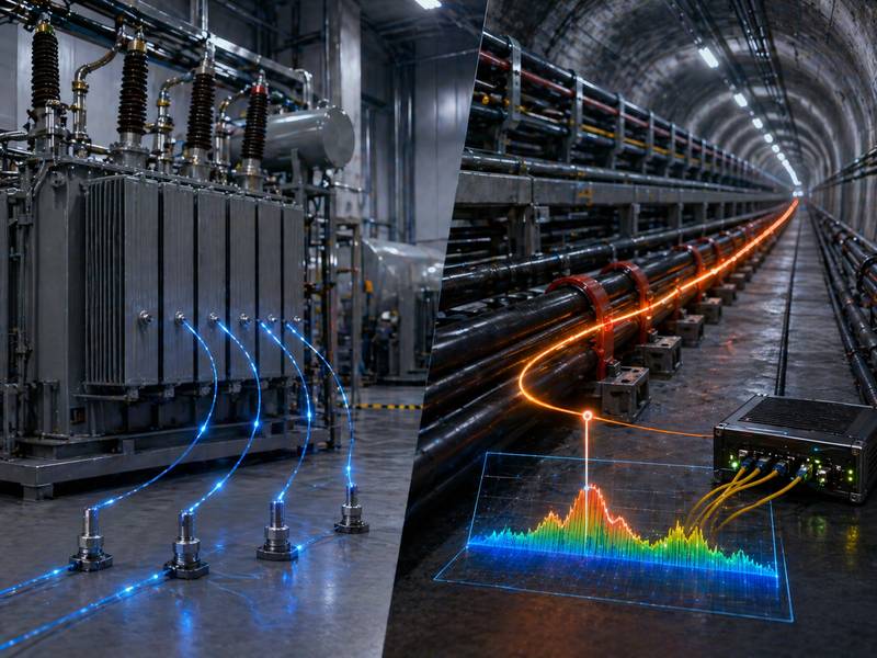
Inaccurate readings are often caused by incorrect calibration, wrong fiber parameters, unsuitable reference temperature, poor contact between the sensing cable and the monitored object, or uneven installation conditions. For instance, a fiber optic cable may not accurately represent the cable surface temperature if it is placed next to a power line but is not securely fastened. If the cable is buried loosely in soil, the measured temperature may lag behind actual hot spots.
To solve this issue, confirm whether the DTS system has been calibrated after installation. Use a known temperature reference point or controlled temperature section when possible. Check whether the fiber type, sensing distance, and channel settings match the actual cable. For applications such as power cable monitoring, pipeline leakage detection, or tank fire detection, improve cable contact with the target object.
Good installation is just as important as device accuracy. A high-quality distributed temperature sensing host cannot provide reliable data if the sensing cable is installed far away from the heat source or exposed to unrelated environmental temperature changes.
Frequent False Alarms
False alarms are a serious problem in distributed temperature sensing systems. If the system sends too many unnecessary alarms, operators may lose trust in the platform. In fire detection or critical equipment protection, this can create operational risk.
False alarms usually happen because alarm thresholds are too low, the rate-of-rise setting is too sensitive, zones are not properly divided, or environmental changes are not considered. Outdoor DTS cables may be affected by sunlight, rain, wind, seasonal temperature changes, nearby equipment, or temporary construction work.
The solution is to use zone-based alarm settings instead of one fixed threshold for the whole route. Different areas should have different alarm values. For example, a tunnel entrance may experience strong temperature changes, while a deep tunnel section may remain stable. A cable tray near heat-producing equipment may need a different alarm threshold than a normal cable corridor.
You can also use multiple alarm levels, such as pre-alarm, warning alarm, and emergency alarm. This helps operators distinguish between normal temperature fluctuation and real risk. Rate-of-rise alarm settings should be adjusted carefully after observing historical temperature data.
Missed Alarms
A missed alarm means the system fails to detect a real abnormal temperature event. This problem is more dangerous than false alarms because it may allow overheating, fire, leakage, or equipment damage to develop without warning.
Missed alarms may be caused by thresholds set too high, poor cable placement, insufficient sampling resolution, wrong zone configuration, or slow response due to weak thermal contact. In some cases, the sensing cable is installed too far away from the actual heat source. The DTS system may work normally, but the heat does not transfer to the fiber quickly enough.
To reduce missed alarms, review the cable route and make sure the sensing fiber is installed near the risk area. For power cable monitoring, the sensing fiber should follow the cable route closely. For pipeline monitoring, the fiber should be positioned where leakage or temperature change can be detected effectively. For fire detection, the cable should be placed according to airflow, heat movement, and site layout.
Alarm thresholds should be based on actual site testing. Do not rely only on factory default values. Run heating tests, simulated fault tests, or controlled temperature tests where possible.
Shorter Sensing Distance Than Expected
Many projects expect the distributed temperature sensing system to monitor several kilometers or even tens of kilometers. However, after installation, the actual sensing distance may be shorter than planned. The far end of the fiber may show poor signal, high noise, or no usable data.
This problem is usually related to optical loss. High splice loss, excessive connector loss, poor cable quality, wrong fiber type, and long route design can all reduce sensing distance. Cable damage during construction may also increase attenuation.
Before installation, the project should calculate the optical budget and select a DTS host suitable for the required distance. During installation, each splice and connector should be tested. After installation, an OTDR test can confirm whether the link loss is acceptable.
If the existing route loss is too high, repair poor splice points, replace damaged sections, reduce unnecessary connectors, or divide the route into shorter monitoring channels. In some projects, using multiple channels or multiple DTS units is more reliable than forcing one channel to monitor an overly long route.
Poor Temperature Resolution or Spatial Resolution
Temperature resolution and spatial resolution affect how clearly the DTS system can identify temperature changes. Poor resolution may make hot spots appear wider, weaker, or less accurate than they really are.
Common causes include unsuitable device selection, long measurement distance, low sampling setting, high optical noise, or incorrect measurement time. Longer averaging time can improve data stability, but it may reduce real-time response. Shorter measurement time improves response speed, but it may increase noise.
The solution is to balance response speed, measurement accuracy, and project requirements. For fire detection, fast alarm response may be more important. For power cable load monitoring, stable long-term temperature data may be more valuable. Choose the DTS system and measurement parameters according to the application, not only the longest distance specification.
Communication Failure
DTS systems are often connected to SCADA, fire alarm systems, security platforms, industrial control systems, or cloud monitoring platforms. Communication failure can prevent alarms and data from reaching operators.
Common causes include wrong IP address, network conflict, damaged Ethernet cable, firewall restrictions, wrong protocol setting, unstable switch, or incorrect integration with third-party platforms. If the relay alarm output is used, incorrect normally open or normally closed wiring can also cause output failure.
Start troubleshooting by checking the DTS host network status. Confirm IP address, gateway, subnet, and communication port. Test the network cable and switch. If the system is connected to a third-party platform, confirm protocol settings and data mapping. For dry contact alarm output, check wiring mode and test alarm output manually.
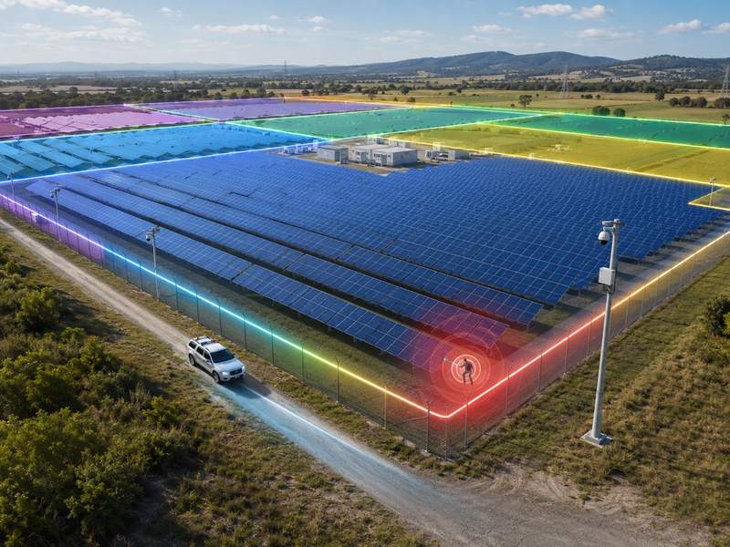
Alarm Location Is Not Accurate
One major advantage of distributed temperature sensing is location-based monitoring. When an alarm occurs, the system should show the approximate distance or zone of the abnormal event. If the location is inaccurate, maintenance teams may waste time searching for the fault.
This problem often comes from incorrect route mapping. The fiber distance in the system may not match the actual physical route. Extra fiber stored in splice boxes, cable loops, detours, or inaccurate zone division can all cause location errors.
To solve this problem, record the actual cable route during installation. Mark splice boxes, reserved fiber sections, loops, and key distance points. In the software, match fiber distance with the site map. For important areas, perform field heating or cooling tests at known points and verify whether the platform location matches the real location.
| Location Problem | Cause | Solution |
| Alarm point shifted | Extra reserved fiber not mapped | Add reserved fiber distance into route data |
| Wrong zone alarm | Defense zone division error | Redefine zones by the real cable route |
| Cannot find a hotspot | Poor site documentation | Update drawings and cable records |
| Map mismatch | Route changed after installation | Reconfigure map and distance calibration |
Environmental Interference
DTS systems measure temperature, so environmental influence must be considered. Outdoor sunlight, rain, snow, ventilation, nearby machines, hot surfaces, steam pipes, and seasonal changes can all affect temperature readings.
Environmental influence is not always a fault. It becomes a problem when the system cannot distinguish normal temperature changes from abnormal events. For example, direct sunlight on an exposed cable may trigger a high-temperature alarm. A ventilation outlet may create repeated temperature changes near the sensing fiber.
The solution is to design alarm logic according to the environment. Use zones, delay settings, rate-of-rise alarms, and historical trend analysis. If necessary, add protective covers, improve cable routing, or move the sensing cable away from strong environmental interference.
Cable Damage During Installation
Fiber optic sensing cables are durable when used correctly, but they can still be damaged by excessive pulling force, sharp bending, crushing, cutting, improper fixing, or poor handling during construction.
A damaged cable may cause signal loss, high attenuation, unstable measurement, or complete channel failure. In buried applications, stones, heavy compaction, or later excavation may damage the cable. In cable tray applications, sharp metal edges may cut the cable jacket.
To prevent this problem, train installers before construction. Use proper cable reels and pulling tools. Follow the minimum bending radius and tensile strength requirements. Protect the cable at corners, joints, and transition points. For buried installation, use warning tape, protective pipe, sand bedding, or mechanical protection where needed.
Inadequate Upkeep and Data Administration
After months or years of use, some DTS issues show up. They may be caused by dirty connectors, aging accessories, damaged splice boxes, changed site conditions, or outdated software settings.
A DTS system should not be installed and forgotten. It needs regular inspection and data review. Maintenance teams should check host status, fiber route, splice boxes, alarm logs, communication records, and historical temperature curves.
Recommended maintenance tasks include:
- Clean and inspect optical connectors regularly.
- Check whether splice boxes are sealed and dry.
- Review alarm records and identify repeated false alarm zones.
- Compare historical temperature curves with current data.
- Update route maps after construction changes.
- Back up system configuration and alarm data.
- Test alarm output and platform communication periodically.
Best Practices for Stable DTS Operation
| Project Stage | Best Practice | Benefit |
| Design | Choose a suitable cable and DTS range | Avoid distance and accuracy problems |
| Installation | Control bending, pulling, and splice loss | Improve signal stability |
| Commissioning | Calibrate temperature and route distance | Improve measurement accuracy |
| Alarm setting | Use zone-based thresholds | Reduce false alarms and missed alarms |
| Integration | Test network and alarm output | Ensure platform linkage |
| Maintenance | Inspect fiber route and review data | Keep the system reliable over time |
Distributed Temperature Sensing provides long-distance temperature monitoring for complex environments, helping detect overheating, fire risks, leakage, and abnormal temperature changes early.
Common DTS problems include weak signals, false alarms, location errors, communication failure, interference, and cable damage. Most can be solved with proper installation, correct settings, inspection, and maintenance.
Stable DTS performance depends on the full system: sensing fiber, host, software, alarm logic, and site conditions.