Blogs

Fiber Optic Temperature Sensor Transformer
Blogs

What Is a Fiber Optic Temperature Sensor for a Transformer?

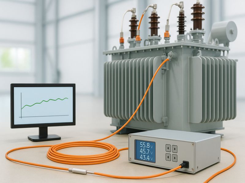
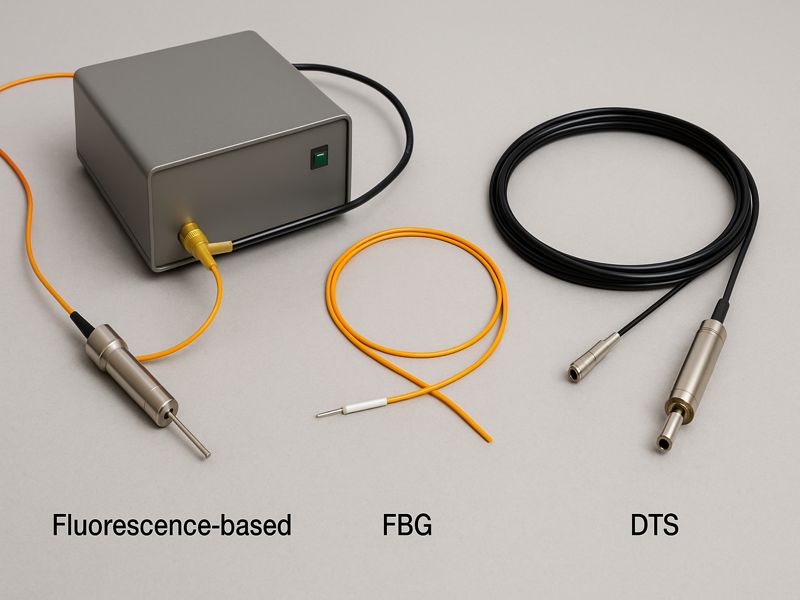
In the power industry, transformer reliability is vital for stable energy distribution. Constant electrical and thermal stress can cause insulation failure or aging if temperatures exceed safe limits. Accurate, continuous monitoring is essential, yet traditional RTDs and thermocouples struggle in high-voltage, oil-filled environments. Fiber optic temperature sensors solve this challenge by using light instead of electricity, offering safe, precise, real-time data even under extreme transformer conditions. The Role of Temperature Monitoring in Transformers Temperature is the most important factor affecting transformer performance and lifespan. Every 6–8°C rise above the design limit can halve the insulation life according to IEEE and IEC standards. Key Monitoring Zones Winding hot-spots: Most critical region, often the cause of insulation failure. Core and yoke: Affects magnetic losses and oil circulation. Oil temperature: Reflects overall thermal behavior and cooling efficiency. When these areas overheat, it leads to oil oxidation, insulation deterioration, and efficiency loss. Thus, maintaining optimal temperatures ensures transformer longevity, safety, and load efficiency. What Is a Fiber Optic Temperature Sensor? A fiber optic temperature sensor is a non-electrical device that measures temperature using light transmission through optical fibers. Instead of relying on electrical resistance or voltage changes, it measures the effect of temperature on light properties such as wavelength, intensity, or fluorescence decay. Main Components Optical Fiber: Carries light signals safely through high-voltage regions. Sensing Probes: Placed at strategic points like winding or oil channels. Signal Conditioner / Interrogator: Converts optical data into temperature readings. Display or Data System: Displays data or sends it to the transformer control unit. Because light is immune to electromagnetic interference and the fibers are non-conductive, fiber optic sensors are intrinsically safe for high-voltage transformer environments. Working Principle of Fiber Optic Temperature Sensors in Transformers Fiber optic sensors operate based on light interaction with temperature-sensitive materials. In transformer applications, two main technologies are used: Fluorescence-based Sensors (Fluoroptic®): These use a temperature-sensitive phosphorescent material at the fiber tip. When illuminated, it emits light that decays over time. The decay rate changes with temperature, allowing precise temperature measurement. Sensors for Fiber Bragg Grating (FBG): The fiber core of FBGs is engraved with tiny gratings. As temperature changes, the reflected wavelength (Bragg wavelength) shifts linearly, giving accurate temperature readings. Simplified Operation Flow Light is emitted from the interrogator into the fiber. The sensor probe at the target location reflects or re-emits light based on temperature. The temperature is ascertained by analyzing the signal that is returned. Results are transmitted to the transformer monitoring system in real-time. This method enables direct, multi-point measurement even inside energized windings—something impossible with electrical sensors. Advantages of Fiber Optic Temperature Sensors in Transformers Fiber optic sensors offer transformative benefits over traditional electrical sensors, particularly in oil-filled power transformers. Key Advantages Electrical Isolation: Non-conductive fibers eliminate short-circuit risks. Immunity to EMI: No interference from high magnetic fields or switching transients. Hot-Spot Accuracy: Direct measurement inside windings where heat originates. Safety: Fully safe in high-voltage oil-filled environments. Durability: Resistant to oil, pressure, vibration, and high voltage. Low Maintenance: No recalibration required over long lifespans. Fast Response: Instant detection of temperature rise during load surges. Fiber Optic vs. Conventional Temperature Sensors Feature RTD / Thermocouple Fiber Optic Temperature Sensor Signal Type Electrical Optical (Light-based) Electrical Conductivity Conductive Non-conductive EMI Sensitivity High None Measurement Location External / surface Directly in winding Accuracy ±2–3°C ±0.5°C or better Safety Risk of electric arc Intrinsically safe Response Time Slow Fast (milliseconds) Maintenance Frequent calibration Virtually maintenance-free Types of Fiber Optic Temperature Sensors Used in Transformers Different fiber optic sensing technologies serve different transformer applications, depending on accuracy, environment, and system size. Type Working Principle Application Accuracy Fluorescence-based Measures fluorescence decay Winding hot-spot measurement ±1°C FBG (Fiber Bragg Grating) Reflects wavelength shifts Core, bushing, external areas ±0.1°C DTS (Distributed Temperature Sensing) Raman/Brillouin scattering analysis Large-scale monitoring along entire transformer ±1°C Fluorescence-based sensors dominate in transformer applications because they can be embedded directly within windings during manufacturing without electrical risk. Key Applications in Power Transformers Winding Hot-Spot Measurement This is the most critical function of fiber optic sensors. Fibers are embedded during transformer coil winding. Sensors measure real-time hot-spot temperature, not estimated values. Data helps adjust load capacity and cooling dynamically. Manufacturers like ABB, Siemens, and GE integrate 4–12 probes per transformer to capture temperature variations between phases and coils. Oil and Core Temperature Monitoring In oil-filled transformers, fibers are placed at different depths within the oil channels. Tracks oil stratification and cooling efficiency. Prevents overheating during overloading or pump failure. Enhances thermal model accuracy. For dry-type transformers, FBG sensors attached to the core detect heat buildup during high current loading. Thermal Modeling and Overload Control FOTS data integrates with thermal models to optimize performance. Enables Dynamic Thermal Rating (DTR) for real-time load adjustment. Provides feedback to automatic cooling control (fans, pumps). Predicts thermal aging and remaining insulation life. This ensures maximum utilization without exceeding thermal limits. Integration with Transformer Monitoring Systems Modern transformers are equipped with digital monitoring systems like SCADA, IoT-based platforms, or proprietary diagnostic units. Fiber optic sensors feed critical temperature data to these systems for centralized control and analytics. Key Integration Features Real-time visualization of winding and oil temperature profiles. Automatic alarms for thermal thresholds. Predictive analytics combining FOTS + Dissolved Gas Analysis (DGA). Data sharing with utility management systems for remote diagnostics. This integration transforms a transformer into a smart asset capable of predictive maintenance and failure prevention. Installation and Maintenance Considerations Installation Sensors are embedded during transformer manufacturing, often near high-current windings. Fibers are routed through sealed feedthroughs to prevent oil leakage. Interrogator units are installed outside the tank for data acquisition. Maintenance Virtually maintenance-free due to immunity from oil contamination and electrical stress. No recalibration is required for over a decade. System verification involves optical signal validation rather than direct probe testing. Installation challenges may occur in retrofitting older transformers, where integrating fibers into existing windings is difficult. Hence, most FOTS are implemented during new transformer production. Challenges and Limitations While fiber optic technology is highly reliable, a
Installing FOIDS for Critical Infrastructure
Blogs

Top 10 Benefits of Installing FOIDS for Critical Infrastructure

Critical infrastructure—power grids, railways, pipelines, airports, and data centers—forms the backbone of modern economies and demands robust protection. Traditional systems like CCTV or motion sensors offer limited coverage, while FOIDS provide continuous, real-time monitoring using fiber cables as sensitive sensors. This article outlines the top 10 benefits of FOIDS, highlighting improved security, lower costs, and regulatory compliance. What Is FOIDS and How It Works FOIDS operates on the principle of distributed fiber optic sensing, where a laser pulse is transmitted along an optical fiber. As the light travels, small portions scatter back due to microscopic variations in the fiber’s structure—a phenomenon known as Rayleigh backscatter. Any disturbance—such as vibration, cutting, digging, or temperature change—alters the backscattered light pattern, which is analyzed by the interrogator unit to pinpoint the location and type of event. Core Technologies Behind FOIDS Distributed Acoustic Sensing (DAS): Detects vibration and acoustic disturbances such as footsteps, vehicles, or drilling. Distributed Temperature Sensing (DTS): Monitors heat buildup and fire events along cables or tunnels. Distributed Strain and Temperature Sensing (DTSS): Combines temperature and strain measurement for detecting ground movement or structural deformation. Unlike point sensors, FOIDS provides continuous coverage—every meter of fiber acts as a detection point. Benefit #1: Continuous Real-Time Monitoring Traditional systems monitor only predefined zones or points. FOIDS transforms the entire fiber length—often spanning tens of kilometers—into a continuous line of defense. Operators can receive instant alerts of intrusion, vibration, or temperature change in real time. This continuous data stream is invaluable for high-risk assets like oil pipelines, border fences, and metro tunnels, where a delay of even seconds can mean catastrophic damage or service interruption. Benefit #2: High Localization Accuracy FOIDS can locate intrusion or disturbance events with pinpoint precision—often within ±1–2 meters. This allows rapid and targeted deployment of patrols or drones to the exact site of the event, minimizing downtime and false investigations. In pipeline or substation applications, precise localization supports automated decision-making, such as isolating a segment or redirecting flow until the issue is resolved. Benefit #3: Multi-Threat Detection Capability A single FOIDS installation can detect multiple threats simultaneously: Vibration or acoustic disturbances: cutting, climbing, or digging. Temperature anomalies: fire, overheating cables, or equipment failure. Ground or structural deformation: landslides or tunnel movement. This versatility means operators can replace several traditional systems with one unified solution. DAS, DTS, and DTSS technologies together deliver comprehensive situational awareness across both security and operational dimensions. Benefit #4: Long-Range Coverage FOIDS can cover 20–50 km per interrogator channel, depending on the fiber type and system configuration. In contrast, most traditional systems require multiple sensors and power sources at short intervals. Technology Typical Range per Unit Coverage Type Power Requirement FOIDS (DAS/DTS) 20–50 km Continuous linear Centralized (none in the field) Microwave / Radar < 500 m Point/sector Distributed field power Vibration Coils / Sensors < 100 m Localized Distributed CCTV Systems Line-of-sight only Sector visual Local power + lighting Benefit #5: Minimal Maintenance and Long Lifecycle Optical fibers are passive components—they contain no electronic parts, need no field power, and are immune to electromagnetic interference. The interrogator unit, typically housed in a control center, performs all detection and analysis remotely. This means fewer field visits, minimal maintenance, and long service lifespans exceeding 25 years. The absence of outdoor electronics also eliminates corrosion and environmental degradation, making FOIDS ideal for harsh or remote conditions such as deserts, offshore platforms, and mountainous borders. Benefit #6: Integration with Existing Infrastructure FOIDS can be integrated seamlessly with modern SCADA, Video Management Systems (VMS), and Access Control Platforms. The system can automatically do the following when an event is detected: Turn on adjacent cameras for visual confirmation. Trigger lighting or alarms. Notify control rooms via existing network protocols (TCP/IP, SNMP, Modbus). This integration turns FOIDS into a central nervous system for infrastructure security, providing real-time insights through a single command interface. Benefit #7: Enhanced Situational Awareness through Analytics Modern FOIDS employ advanced AI and machine learning algorithms that continuously learn from their environment. They can distinguish between a genuine intrusion (e.g., human activity or vehicle vibration) and environmental noise (e.g., wind, rain, or animal movement). This pattern-based learning dramatically reduces false alarm rates—an essential factor for mission-critical environments where alarm fatigue can lead to delayed responses. FOIDS data can also be fed into predictive analytics platforms, providing early warnings of repetitive disturbances before they escalate into security breaches. Benefit #8: Cyber-Physical Security and Regulatory Compliance Governments worldwide are implementing stricter Critical Infrastructure Protection (CIP) regulations that require continuous monitoring and traceable event logging. FOIDS supports this compliance by offering: Encrypted communication channels. Role-Based Access Control (RBAC) for operator authentication. Audit trails and event logs that can be used for regulatory reporting or forensic analysis. By meeting these cybersecurity and physical protection requirements, FOIDS helps operators align with standards such as NERC CIP, EU CER Directive, and ISO/IEC 27001. Benefit #9: Cost Efficiency Over Long Distances While the initial investment in FOIDS equipment may be higher than in point sensors, the lifecycle cost is significantly lower. Reasons include: No distributed electronics or power along the fence or route. Lower maintenance frequency. Centralized monitoring for multiple zones via a single interrogator. Cost Factor Traditional Systems FOIDS Savings (Approx.) Field Hardware High (many units) Minimal (fiber only) 40–60% Power & Cabling Distributed power Centralized 30–50% Maintenance Frequent site visits Remote diagnostics 50–70% Service Life 8–10 years 20–25 years Longer lifespan Over the system’s lifetime, FOIDS often proves to be the most cost-effective solution per kilometer of protection. Benefit #10: Future-Proof Scalability FOIDS platforms are highly scalable. As infrastructure expands, operators can: Extend fiber coverage without replacing the entire system. Add new channels to interrogators for additional zones. Upgrade firmware to enhance detection algorithms. Because the sensing medium (fiber) is passive and future-compatible, FOIDS can integrate with emerging technologies like digital twins, smart infrastructure analytics, and AI-driven command centers. Real-World Applications and Case Studies Power and Energy A major power utility deployed FOIDS around 12 substations to prevent copper theft. After installation, theft

Fiber Optic Temperature Sensor
Blogs

How to Choose the Right Fiber Optic Temperature Sensor for Your Application

As industries push for greater efficiency and safety, demand for advanced sensing has surged. Fiber optic temperature sensors (FOTS) have emerged as a transformative solution, using light instead of electricity for precise, interference-free monitoring in harsh, high-voltage, or explosive environments. Choosing the right FOTS is essential—an incorrect match risks inaccurate readings or integration issues. Whether for power, oil, aerospace, or medical applications, proper selection ensures accuracy, reliability, and long-term performance. Understanding Fiber Optic Temperature Sensors Basic Working Principle A fiber optic temperature sensor measures temperature by detecting changes in light transmitted through an optical fiber. These changes occur due to variations in physical properties such as refractive index, fluorescence decay, or Bragg wavelength shifts. Because the signal is optical rather than electrical, the system is immune to EMI (Electromagnetic Interference) and suitable for electrically noisy or hazardous areas. Comparison with Traditional Sensors Unlike thermocouples or resistance temperature detectors (RTDs), fiber optic sensors: Provide long-distance sensing (up to tens of kilometers). Operate safely in high-voltage or explosive environments. Offer multi-point or distributed sensing capabilities. Require minimal maintenance and recalibration. Main Types of Fiber Optic Temperature Sensors Type Principle Temperature Range Accuracy Typical Application Fluorescence-based Measures the fluorescence decay time of the doped material −200 °C to +450 °C ±0.5 °C Aerospace, cryogenic, R&D FBG (Fiber Bragg Grating) Detects wavelength shift from Bragg reflection −40 °C to +300 °C ±0.2 °C Transformers, motors, medical DTS (Distributed Temperature Sensing) Uses Raman/Brillouin backscatter for continuous temperature mapping −40 °C to +600 °C ±1 °C per km Pipelines, tunnels, cables Each type excels in specific conditions. FBG sensors deliver high precision at localized points, while DTS offers real-time profiling across long distances — ideal for infrastructure and process industries. Key Selection Criteria Choosing the right fiber optic temperature sensor requires balancing multiple technical and environmental factors. Below are the most critical parameters to evaluate. Temperature Range and Sensitivity Different sensors handle different temperature extremes. Fluorescent-based sensors perform well at ultra-low or ultra-high temperatures, while FBGs are optimized for moderate industrial ranges. Always match the sensor’s operational limit with your process requirements to avoid signal drift or damage. Number of Measurement Points If you need a few discrete readings (e.g., transformer hotspots), an FBG sensor array is sufficient. However, if your goal is continuous monitoring along a 10 km pipeline, a DTS system is necessary. Understanding whether your application requires point, multi-point, or distributed sensing is a key decision factor. Installation Environment Temperature sensors are often deployed in demanding conditions: high vibration, strong electromagnetic fields, or exposure to chemicals. Choosing the right fiber coating — such as polyimide for high-temperature tolerance or stainless-steel armoring for mechanical protection — ensures longevity. Accuracy and Resolution Precision matters in industries like aerospace or semiconductor manufacturing, where even minor temperature variations can cause material expansion or electronic drift. High-quality FBG sensors can achieve sub-degree accuracy, while DTS provides broader but less fine-grained data. Response Time In dynamic environments (e.g., engine testing or turbine monitoring), response time is critical. FBG sensors typically offer millisecond response, ideal for capturing transient events, whereas DTS response time is slower due to signal averaging along the fiber length. Compatibility with Existing Systems Integration ease affects the total cost of ownership. Verify that the optical interrogator supports your desired sampling frequency, communication protocol (Ethernet, Modbus, etc.), and software interface for SCADA or predictive-maintenance systems. Sensor Type vs. Application Matrix The following matrix summarizes which sensor types fit common industrial uses. Application Recommended Sensor Type Why It Fits Power Transformers FBG Detects localized hot-spots, immune to EMI Oil Wells DTS Monitors distributed temperature over kilometers Aerospace Engines Fluorescence Ultra-fast response, compact form factor Medical Devices Mini FBG Biocompatible, precise at the small scale Power Cables & Tunnels DTS Continuous thermal mapping for fault detection Nuclear Facilities Radiation-hardened FBG Resists radiation and high heat By aligning sensor type with your environment, you can prevent over-engineering (and overspending) while ensuring reliability. Environmental and Operational Considerations The surrounding environment has a direct impact on sensor durability and performance. Fiber Coating Materials: Polyimide – Excellent for high-temperature (up to +400 °C). Acrylic – Flexible and cost-effective for general use. Metal-coated fibers – Provide superior mechanical and chemical resistance. Pressure & Radiation: In nuclear or deep-sea settings, sensors must endure pressure fluctuations and radiation exposure. Specialized fiber types such as radiation-hardened silica fibers are essential. Moisture & Chemical Protection: Chemical plants or subsea systems require hermetically sealed connectors and protective sheaths to prevent water ingress or corrosion. Connectivity to Monitoring Systems Hardware and software must work together seamlessly for modern sensor systems to function. Optical Interrogators The interrogator converts optical signals into digital temperature data. Selection factors include: Wavelength range and resolution Sampling rate (up to 1 kHz for fast systems) Channel capacity (number of sensors) Data Acquisition and Analytics Fiber optic systems are often tied into SCADA or predictive maintenance software. Real-time analytics can flag anomalies, enabling condition-based maintenance instead of reactive repair. Calibration and Accuracy Assurance Even optical sensors require periodic calibration to ensure stability. Some manufacturers offer automatic recalibration algorithms or reference FBGs embedded within the fiber network. Trade-offs between Cost and Performance Although fiber optic sensors are more expensive initially, they usually save downtime and maintenance costs. Configuration Initial Cost Accuracy Maintenance Typical Use Single FBG Low ±0.2 °C Minimal Laboratory, transformer monitoring Multi-FBG Array Medium ±0.3 °C Low Industrial automation DTS System High ±1 °C Very Low Pipelines, tunnels, power cables A cost-benefit analysis helps determine ROI. For instance, in a power plant, installing FBG sensors may prevent a transformer failure that could cost millions in repairs and downtime. Thus, long-term savings often outweigh initial investment. Certification and Reliability Standards To ensure compliance and interoperability, consider the following standards: IEC 61757 – Defines testing and calibration for fiber optic sensors. IEEE C57.148: Recommendations for transformer temperature monitoring. The ASTM E2847 standard pertains to distributed fiber optic sensing. MIL-STD-810 – Environmental testing for aerospace and defense sensors. Choosing certified products not only guarantees performance but also simplifies

Railway with Fiber Optic Detection Systems
Blogs

Railway and Metro Tunnel Safety with Fiber Optic Detection Systems

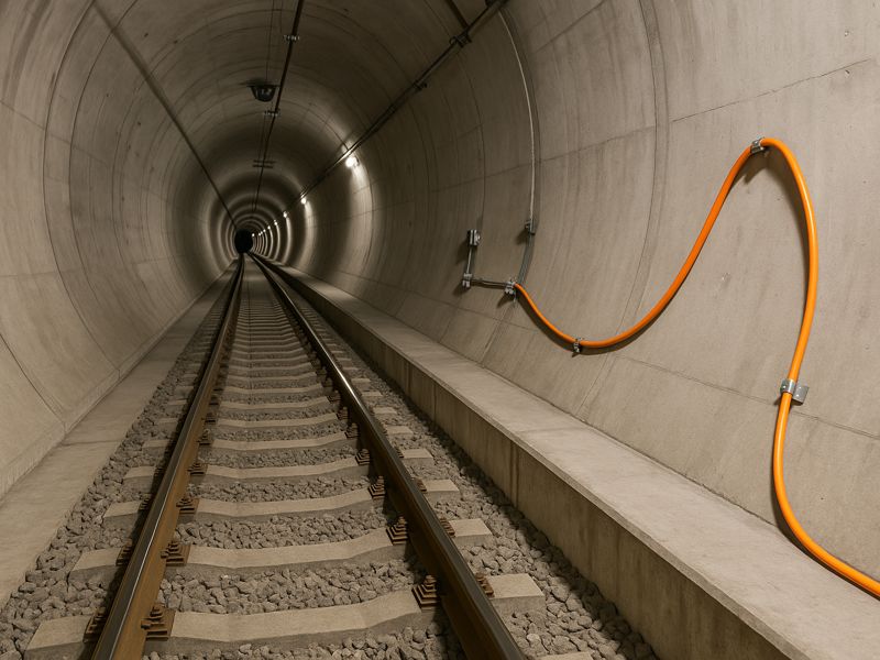
Railway and metro tunnels are vital transport links handling heavy traffic in confined spaces where safety failures can be catastrophic. Traditional monitoring—using discrete sensors or manual checks—offers limited coverage and slow response. Fiber optic detection now enables continuous, real-time monitoring, transforming cables into distributed sensors that detect vibration, strain, temperature, and movement with precision. This article explores how such systems enhance tunnel safety, their key applications, and future innovations in rail monitoring. Understanding Fiber Optic Detection Systems Fiber optic detection systems operate on the principle of light backscatter analysis. Microscopic flaws in the glass cause some of the light that a laser pulse passes through an optical fiber to be scattered back. Variations in backscattered signals reveal environmental changes along the fiber—such as vibration, temperature shifts, or strain. Three core sensing technologies are used in tunnel applications: Technology Function Common Use Case Distributed Acoustic Sensing (DAS) Detects vibrations and acoustic disturbances Intrusion, rail faults, rockfalls Distributed Temperature Sensing (DTS) Measures temperature along the fiber Fire and heat detection Distributed Strain and Temperature Sensing (DTSS) Tracks both strain and temperature Structural deformation monitoring These systems provide continuous coverage over kilometers with no electronic components inside the sensing zone—making them durable, EMI-resistant, and low-maintenance. In tunnels where conditions are harsh and access is limited, these features translate into exceptional reliability. Safety Challenges in Railway and Metro Tunnels Tunnel environments combine several risk factors that demand constant vigilance: Structural and geological instability: Ground movement, rock deformation, or subsidence may stress tunnel linings. Fire and overheating: Equipment failures or cable fires can spread rapidly in enclosed tunnels. Unauthorized access or intrusion: Human or vehicle entry through maintenance shafts or portals can endanger operations. Track and rolling stock failures: Rail cracks, wheel impacts, or dragging components pose accident risks. Environmental hazards: Flooding, gas leakage, or electrical faults in confined spaces are hard to detect early. Given these challenges, traditional point-based sensors are inadequate. Fiber optic systems overcome this by offering distributed, real-time monitoring, transforming every meter of fiber into a safety sensor. How Fiber Optic Detection Enhances Tunnel Safety Continuous and Distributed Monitoring Unlike discrete sensors, fiber optic systems provide complete linear coverage. Every meter of the optical fiber acts as a detection node, ensuring no blind spots from portal to portal. Real-Time Event Localization The system can pinpoint the exact position of a vibration, heat source, or strain change—often within ±1–2 meters. This precision accelerates response and minimizes downtime. Multi-Hazard Detection One fiber can simultaneously detect vibration, temperature, and strain, offering multi-threat awareness (fire, intrusion, structural damage, or rail issues). Seamless SCADA Integration Fiber systems interface directly with tunnel SCADA (Supervisory Control and Data Acquisition) and VMS (Video Management Systems). When a heat or vibration anomaly is detected, the control center can automatically trigger ventilation, cameras, or alarms. Key Applications in Tunnel Safety Fiber optic detection systems are adaptable across multiple hazard categories: Application Area Primary Fiber Type Typical Benefits Fire & Heat Detection DTS Early warning of temperature rise and fire spread Structural Health Monitoring DTSS Detect lining strain, cracks, and settlement Intrusion Detection DAS Detect unauthorized entry or vandalism Track Fault Detection DAS Identify broken rails, dragging gear, or wheel impacts Rockfall / Ground Movement DAS / DTSS Detect seismic vibrations or tunnel roof instability These applications are particularly critical for long tunnels, underground metro lines, and mountainous railway corridors where physical inspection is impractical. System Architecture and Deployment Considerations A well-engineered deployment plan ensures reliability and precision. Fiber Placement: Cables are installed along tunnel walls, under tracks, or within cable trays. Buried configurations offer better vibration coupling for DAS, while wall-mounted routes are ideal for DTS fire detection. Installation Methods: Depending on the environment, fibers can be embedded, clamped, or run through protective ducts to ensure long-term durability. Signal Processing: The interrogator unit (DAS/DTS device) captures backscatter data and applies AI-based classification algorithms to filter noise and identify meaningful events. Localization and Calibration: Mapping fiber distance to tunnel coordinates is critical for accurate event positioning. Reference markers and calibration runs help maintain precision. Maintenance: Systems require minimal upkeep but should be periodically checked for optical loss, mechanical damage, and calibration drift. Case Studies and Real-World Implementations Case 1: Metro Tunnel Fire Detection in Europe A large metropolitan subway network implemented a Distributed Temperature Sensing (DTS) system along a 5-kilometer twin-tube tunnel. The system detected overheating in a cable tray before smoke appeared, enabling ventilation activation within 20 seconds and preventing service disruption. Result: 85% reduction in fire response time compared to traditional smoke sensors. Case 2: Mountain Railway Rockfall Monitoring in Asia A high-speed rail tunnel under mountainous terrain adopted DAS-based rockfall detection. The system identified impact vibrations near the tunnel entrance during heavy rainfall, automatically signaling maintenance crews. Result: Early alerts prevented potential derailment, saving millions in equipment repair costs. Case 3: Combined Safety and Structural Health in Metro Lines An urban rail operator combined DTS (for fire) and DTSS (for strain) along newly built tunnels. Data integration with the central SCADA system allowed unified monitoring dashboards for both safety and maintenance. Challenges and Limitations Challenge Description Mitigation Strategy Calibration Complexity Tunnel acoustics and material composition vary Use environment-specific AI models and adaptive calibration False Alarms Noise from passing trains or maintenance Implement pattern recognition and event validation logic Retrofitting Costs Integrating sensing fiber into existing tunnels can be costly Utilize spare or dark fibers in communication cables Data Management High-frequency data streams require robust storage Deploy edge processing and compressive analytics Environmental Harshness High humidity and vibration stress fiber hardware Use ruggedized, armored fiber cables and sealed enclosures Despite these limitations, operational benefits often outweigh initial installation challenges. Future Trends in Tunnel Fiber Optic Monitoring Artificial Intelligence and Machine Learning Next-generation systems use AI/ML models to classify acoustic or vibration patterns, distinguishing between a human intruder, equipment noise, or natural seismic events. This drastically lowers false alarm rates. Multi-Sensor Fusion Manufacturers are integrating DAS + DTS + DTSS into hybrid systems for simultaneous detection of vibration, temperature, and

Global Market Trends in Fiber Optic Intrusion Detection Systems
Blogs

Global Market Trends in Fiber Optic Intrusion Detection Systems

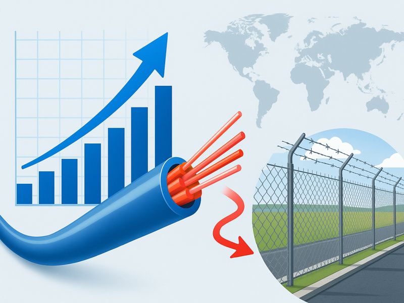
FOIDS use optical fibers as continuous sensors to detect and classify disturbances across perimeters, buried lines, and linear assets. Adoption has surged recently due to growing infrastructure threats, maturing DAS technology, stricter monitoring regulations, and lower lifetime costs. The broader DAS market—valued at ~$0.6–0.8B in 2023–2025—is expanding steadily with strong growth projected through 2030. Meanwhile, dedicated estimates for fiber-optic perimeter intrusion solutions point to a smaller but briskly growing sub-segment, supported by fence-, wall-top-, and buried-cable deployments at high-security sites. What’s Driving Demand 1) Critical Infrastructure And Linear Assets Pipeline operators, railways, and utilities are turning to FOIDS/DAS to detect third-party interference (TPI), leaks, ground movement, theft/tamper events, or animal/human intrusions—use cases where continuous coverage and pinpoint localization matter more than adding more discrete sensors. This “continuous sensing” value proposition strongly differentiates fiber from legacy point sensors. 2) Lower Total Cost Over Distance When protecting tens to hundreds of kilometers, FOIDS often beats traditional sensors on cost per kilometer because a single interrogator channel can cover long runs (dozens of km) with precise localization. System examples publicly cite long-range coverage and multi-topology mounting (fence, buried, wall-top). 3) Analytics, Ai/Ml, And Fewer Nuisance Alarms Modern classifiers trained on vibration signatures reduce nuisance alarms from wind, rain, or vehicles, while enabling event labeling (cut vs climb vs dig). Railway research highlights ML-based intrusion classification to improve safety outcomes and response speed, reflecting a wider market shift to analytics-first FOIDS. 4) Compliance and Insurer Expectations Security standards for energy, transportation, and data-center perimeters are pushing continuous monitoring and tamper-evident controls, nudging buyers toward technologies that document detection performance and service levels—an area where FOIDS/DAS data logs and auditability are compelling. Market Sizing Context: FOIDS within the DAS Universe Most published market numbers track DAS, the core technology behind many FOIDS. Representative analyst cuts include: Grand View Research: global DAS valued $627.9M (2023), CAGR ~10.9% (2024–2030). Mordor Intelligence: DAS $0.77B (2025), to $1.12B (2030) at ~8.2% CAGR Global Market Insights: DAS $635M (2023), >9.5% CAGR (2024–2032). Segment-level reports aimed specifically at fiber-optic perimeter intrusion show a smaller, security-focused market with steady growth into the 2030s. Treat these as directional (methods vary), but they align with the broader DAS growth story. Technology Trends Redefining FOIDS A) From Hardware-Centric To Analytics-Centric Next-gen interrogators still matter (dynamic range, channel count, sampling rate), but buyers are increasingly choosing platforms—where detection performance comes from signal processing and AI/ML models tuned to the environment (fence fabric, soil type, traffic pattern). Vendors emphasize adaptive algorithms to maintain probability of detection (Pd) while suppressing nuisance alarms. B) Multi-Topology Flexibility Best-of-breed systems support fence-mounted, buried, and wall-top modes on the same platform, reducing SKU sprawl and simplifying lifecycle management. This flexibility helps integrators standardize across sites. C) Open Integration With Psim/Vms And Soar FOIDS data is most valuable when fused with video, access control, and radar. Open APIs and certified integrations with VMS/PSIM platforms are now table-stakes, driving faster operator response and enabling alarm-to-video verification workflows—another lever against nuisance alarms. D) Edge + Cloud Architectures Edge inference minimizes latency and bandwidth, while cloud analytics enable fleet learning across sites (e.g., recognizing a new dig signature). Expect hybrid deployments where sensitive raw acoustic data stays local, but metadata and models sync centrally. E) Cyber-Hardening Of Physical Security Systems As FOIDS joins IT/OT networks, buyers demand secure-by-design devices (signed firmware, role-based access, encrypted comms) and secure remote service. This trend mirrors CIS benchmarks in OT and aligns with zero-trust programs in critical infrastructure. Adoption Patterns By Vertical Vertical Primary FOIDS Roles Notes Oil & Gas (midstream, terminals) Third-party interference, digging, leak/flow anomaly adjunct, perimeter cut/climb DAS widely used along pipelines; FOIDS complements SCADA & pigging. Congruence Market Insights+1 Rail & Transit Intrusion (trespass, animals), rockfall/landslide detection near rights-of-way ML-assisted classification reducing false trips; supports safety KPIs. MDPI+1 Power & Utilities Substation fence protection, cable tunnels, right-of-way monitoring ADSS fiber paths can carry sensing; PSIM/VMS integration is common. Global Market Insights Inc. Data Centers Fence/wall-top detection with video verification FOIDS adopted for large campuses with long perimeters. Airports & Ports Fence/ground intrusion, shoreline or fence-line tapping Environmental noise demands robust analytics; integration with radar. Correctional & Defense High-security perimeters, buried detection zones Long-range localization beneficial for response playbooks. Regional Outlook North America: Mature adopter base in energy, utilities, and data-center campuses. Growth tied to grid modernization, pipeline TPI mitigation, and federal critical-infrastructure guidance. DAS market momentum corroborates steady spend. Europe: Demand driven by rail modernization and critical infrastructure mandates. Environmental noise sensitivity and privacy regulation elevate the value of non-imaging, privacy-preserving sensing like FOIDS. Middle East: Above-average adoption for oil & gas and large industrial perimeters; long linear assets make FOIDS’ economics attractive. Asia-Pacific: Fastest relative growth—railway expansion, ports, airports, and new energy corridors. Research output around railway intrusion monitoring indicates active innovation and pilots turning into programs. Latin America & Africa: Select deployments around mining, pipelines, and national energy assets; projects often tied to public–private security programs. Competitive Landscape: Convergence and Specialization The supplier map includes specialist FOIDS vendors and broader perimeter-security companies integrating fiber into multi-sensor platforms: Specialist fiber-optic security: Future Fibre Technologies (FFT), Fiber SenSys (FSI), Senstar (FiberPatrol) are visible in reference deployments and product collateral, with fence, wall-top, and buried solutions. DAS ecosystem: A wider field provides interrogators and analytics spanning security and industrial monitoring; overall market health here is a bellwether for FOIDS. What buyers will notice: vendors differentiating on (1) algorithmic performance in noisy environments; (2) integration depth with VMS/PSIM; (3) ease of tuning/commissioning; (4) multi-topology support; and (5) lifecycle services. Procurement And Deployment Trends 1) Performance Guarantees & Outcome-Based SLAs Instead of box-spec comparisons, large buyers are requesting site-specific acceptance tests (Pd, FAR/NAR, localization accuracy, environmental robustness) and service SLAs (response, retraining models, firmware cadence). 2) Proof-of-Value Pilots With ClearKPIs Common KPIs: detection probability for defined threats (cut, climb, dig), localization error (± meters), mean time to detect (MTTD), and false/nuisance rates under wind/rain. Multi-week pilots across day/night and weather regimes are becoming standard. 3) Lifecycle Attention: Trenching

Protect Fiber Optic Cable Outside
Blogs

How to Protect Fiber Optic Cable Outside: A Complete Guide

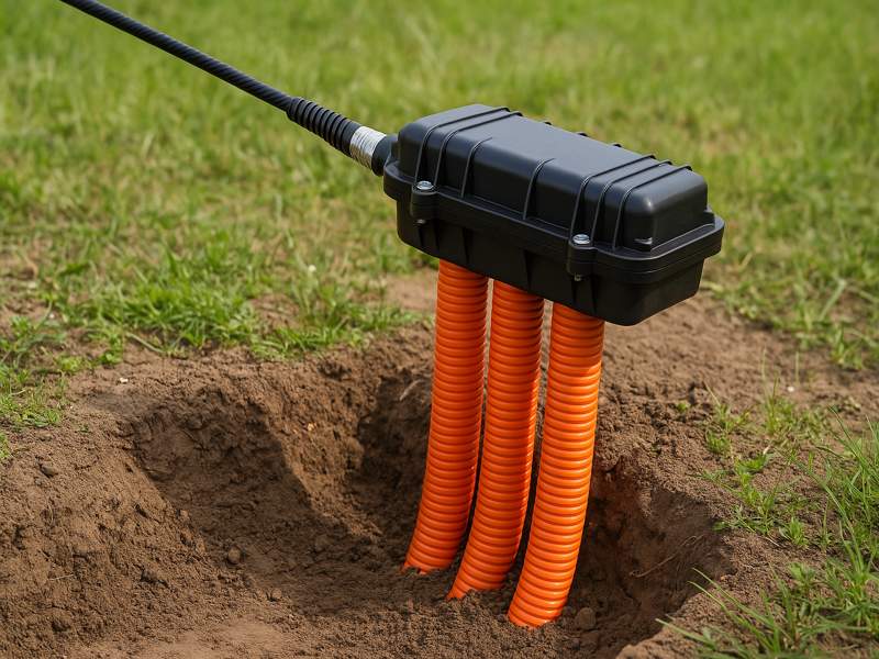
Fiber optic cables enable high-speed, long-distance data transfer, forming the backbone of modern communication. Yet, outdoors, they face temperature swings, moisture, UV exposure, rodents, and human interference. Protecting them is essential for long-term reliability. This guide covers how to safeguard outdoor fiber optics across underground, aerial, direct-burial, and exposed setups. Understanding Outdoor Fiber Optic Cable Risks Before applying protective measures, it’s essential to understand the main risks fiber optic cables face outdoors. Environmental Conditions UV Exposure: Prolonged sunlight degrades standard plastic jackets, making them brittle. Temperature Extremes: Expansion and contraction can cause stress fractures. Moisture & Flooding: Water ingress can damage fibers or connectors, leading to signal attenuation. Wind and Ice: Overhead installations face tension and sagging from strong winds and ice loading. Mechanical and Physical Threats Rodent Damage: Rats and other animals chew through cables, especially in rural or underground installations. Crushing or Impact: Vehicles, construction equipment, or falling branches can compress or sever cables. Soil Shifting: Underground cables may stretch or deform as soil settles or freezes. Human Interference Accidental Digging: Construction activities pose the highest threat to underground cables. Vandalism or Theft: Exposed fiber infrastructure can be deliberately cut or stolen for scrap metal components. Identifying these threats allows network planners and technicians to choose the right protection methods. Selecting the Right Outdoor Fiber Optic Cable Cable protection begins at the selection stage. Not all fiber optic cables are suitable for outdoor environments. Outdoor Cable Types Cable Type Protection Features Common Applications Armored Cable Steel or aluminum armor resists rodent bites and mechanical stress Direct burial, industrial sites Loose Tube Cable Gel-filled tubes prevent water ingress Underground duct and conduit systems Aerial Cable (ADSS) Self-supporting with aramid yarn strength Power line or pole-mounted routes Direct Burial Cable UV-resistant, water-blocked, and armored Long-distance rural or cross-country links Duct Cable Designed for pulling through conduits Urban areas with existing pipe infrastructure Selecting the right cable type ensures that the structure itself provides first-level protection. Material Considerations UV-Resistant Jackets (PE or LSZH): Prevent sunlight degradation. Water-Blocking Gel or Tape: Stops moisture migration inside the cable. Metal or Non-Metallic Armoring: Adds crush and rodent resistance. Ripcord Design: Simplifies access for maintenance without damaging fibers. Underground Fiber Optic Cable Protection Underground installation offers natural protection from wind, ice, and UV exposure—but it also introduces risks like moisture and accidental digging. Use of Conduits and Ducts Installing cables inside conduits or HDPE ducts provides strong mechanical and environmental protection. HDPE Conduits: Flexible and resistant to corrosion and chemicals. PVC Conduits: Ideal for urban environments but less impact-resistant. Sub-ducting: Allows multiple fiber cables inside one main conduit for scalability. Color Coding: Simplifies cable identification during maintenance. Depth and Burial Practices To avoid unintentional injury, the burial depth must be appropriate. Installation Area Recommended Depth Urban Sidewalks 45–60 cm Road Crossings 90–120 cm Agricultural or Rural Areas 60–90 cm Use warning tapes 30 cm above the conduit to alert excavators before reaching the cable. Moisture and Water Protection Even in conduits, water can seep in due to condensation or floods. Seal both ends of the ducts with end plugs or foam seals. Use water-blocking compounds or dry core technology to prevent water migration. Elevate handholes or access points to reduce water accumulation. Protection from Insects and Rodents Network disruptions are frequently caused by rodent attacks. Choose steel-armored or corrugated aluminum-tape cables. Add rodent-resistant conduits or coatings. For high-risk areas, apply rodent repellent compounds during installation. Aerial Fiber Optic Cable Protection Aerial installation is common for rural broadband, power utilities, and city-wide fiber networks. However, exposure to weather and mechanical stress is high. Proper Tensioning and Sag Control Maintain recommended tension and sag during installation to avoid fiber strain. Use dead-end grips or messenger wires for support. Follow manufacturer guidelines for minimum bend radius. UV and Weather Protection Use UV-stabilized cable jackets. Periodically inspect for cracks or discoloration due to sunlight. Install drip loops at connection points to prevent water ingress. Lightning and Electrical Hazards For installations near power lines: Use ADSS (All-Dielectric Self-Supporting) cables to prevent electrical conduction. Ground all metal hardware and avoid contact with high-voltage lines. Maintain safe clearance distances as per local utility standards. Wind and Ice Load Management Use helical cable ties and aerial spacers for wind control. Select cable types rated for ice loading if used in cold climates. Avoid installing cables in deep sags or tree canopies. Direct Burial Cable Protection Direct burial saves time and materials but requires robust protection measures. Armoring and Sheathing Always use armored direct-burial cables with double jackets and water-blocking layers. Backfilling Materials Avoid sharp stones or debris that may pierce the jacket. Use sand or fine soil bedding to cushion the cable. Compact backfill to prevent shifting over time Warning and Identification Install a warning mesh or tape above the buried cable path. Use brightly colored, durable polyethylene tapes. Include warning text such as “Fiber Optic Cable Below – Do Not Dig.” Route Mapping Maintain accurate as-built drawings and GPS coordinates for all buried cable routes. This prevents accidental cuts during future excavation. Protecting Fiber Connections and Enclosures Cable protection extends beyond the fiber itself—connectors, splices, and enclosures must be safeguarded from environmental and mechanical damage. Splice Closure Protection Use IP68-rated waterproof closures. Employ heat-shrink sleeves or gel seals for joint protection. Mount closures in handholes, manholes, or pole enclosures to reduce stress. Connector Enclosures Outdoor connectors should be in weatherproof boxes or fiber distribution cabinets. Maintain proper strain relief to prevent fiber pullout. Use dust caps and sealing gaskets to block contaminants. Grounding and Bonding For metallic-armored cables: Ground at both ends to prevent voltage buildup. Use grounding kits with corrosion-resistant clamps. Verify bonding continuity regularly during inspections. Additional Protective Techniques and Accessories Cable Markers and Signs Use durable cable route markers at regular intervals and key points (turns, junctions, or road crossings). Ensure the information includes cable type, owner, and emergency contact. Conduit Sealing and Pressurization In flood-prone areas: Apply pressurized air or nitrogen in ducts to detect leaks. Seal

What Is Fiber Optic Intrusion Detection
Blogs

What Is Fiber Optic Intrusion Detection and How Does It Work?

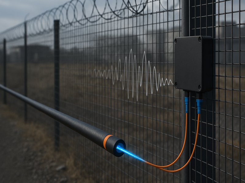
Fiber optic intrusion detection uses specialized cables to sense and report any unauthorized access or disturbance along a protected area. You can think of these cables as a sensitive tripwire or a microphone that listens for unusual vibrations. Unlike traditional electronic sensors, fiber optic systems can detect disturbances over long distances and remain reliable even in challenging environments. You gain better protection because these systems sense tiny changes in the fiber, making them less likely to miss an intrusion. Key Takeaways Fiber optic intrusion detection uses light signals to sense disturbances, making it more reliable than traditional electronic systems. These systems can cover long distances and detect even small changes, ensuring better security for sensitive areas. Advanced algorithms help reduce false alarms, allowing the system to focus on real threats while ignoring harmless events. You can use fiber optic systems for various applications, including perimeter security, infrastructure protection, and data centers. Knowing how this technology operates enables you to select the best option for efficiently safeguarding your assets. Intrusion Detection Overview What It Is You can think of fiber optic intrusion detection as a security system that uses light instead of electricity to sense threats. These systems use fiber optic cables to monitor for changes caused by physical disturbances. When someone tries to climb a fence, cut a cable, or tamper with a protected area, the system detects changes in the light signals traveling through the fiber. This method sets fiber optic systems apart from traditional intrusion detection technologies, which often rely on electronic signals or analyze network traffic. Fiber optic systems stand out because they: Transmit light signals through cables, not just electronic signals. Detect disturbances by monitoring changes in light, not just electrical changes. Respond to physical interactions, such as vibrations or pressure, which alter the light signal. You can find several types of fiber optic intrusion detection systems, each designed for specific needs. The table below shows some popular options and their features: System Type Features Aura Ai-X Data-driven technology with deep learning reduces nuisance alarm rates while maintaining high detection probability. Secure Fence Efficient on a variety of fence types, such as palisade, chainmesh, chain-link, and weldmesh. Secure Point Dual zone system with high sensitivity and low nuisance alarms, adaptable to almost all fence types. Aura Ai-XS Fence-mounted sensing up to 10 km, with precise intrusion detection within ±2 m. Aura Ai-XS (powered by FFT ATLAS) Continuous monitoring and maintenance for optimal performance of the intrusion detection system. Purpose You use fiber optic intrusion detection to protect sensitive areas from a range of threats. These systems help you detect: Unauthorized access, such as cable tapping or attempts to breach a perimeter. Suspicious activities, including unusual movements or behaviors near protected zones. Physical damage to cables can create vulnerabilities and risk data breaches. Organizations choose fiber optic intrusion detection for several reasons. The table below outlines the main objectives: Objective Description Accurate detection of intrusions Ensures that any unauthorized access is identified promptly. Resilience against tampering The system is designed to trigger alarms if the cables are cut or tampered with. Low false alarm rates Capable of distinguishing between real threats and environmental factors, reducing unnecessary alerts. Quick response times Real-time detection allows for immediate action to be taken in case of a security breach. Cost-effectiveness Although initial costs may be higher, long-term savings on maintenance and reliability are significant. Scalability It can be deployed over large areas, making it suitable for extensive perimeters. Reliable performance Continuous monitoring ensures consistent security coverage. You measure the effectiveness of these systems by looking at several factors: Reliability, which means the system works even during outages. Accuracy, which helps you avoid false alarms. Capabilities, so you can keep up with the latest detection features. Maintenance, since low-maintenance systems save you time and money. Coverage, which ensures you detect intrusions precisely. Integrations, so your system works well with other security technologies. Fiber optic intrusion detection gives you a reliable way to secure perimeters. The cables detect stress or breaks when someone tries to breach the area. This technology resists interference, making it a strong choice for organizations that want dependable security.  How It Works Sensing Disturbances You rely on fiber optic cables to act as sensitive detectors along your perimeter. These cables use light to sense even the smallest physical changes. When someone tries to climb a fence, dig near a buried cable, or tamper with a protected area, the cable picks up the disturbance. The system then analyzes these changes in the light signal to determine if an intrusion has occurred. Fiber optic cables can detect several types of disturbances in real-world security scenarios: Vibration Detection: The system senses vibrations caused by footsteps, digging, or cutting. Technologies like fiber Bragg gratings (FBG) and distributed acoustic sensing (DAS) help you secure the physical layer of your perimeter. Polarization Changes: Some systems use polarization-sensitive techniques to spot changes in the way light travels through the cable. This helps you identify disturbances that might not cause strong vibrations. Interferometric Methods: Advanced systems use interferometers, such as Mach–Zehnder and Michelson types, to pick up subtle vibrations. These methods work well for perimeter security and can detect even light touches. Tip: Fiber optic cables are perfect for isolated locations or expansive perimeters because they can detect disruptions over long distances. Environmental factors can sometimes mimic intrusion attempts. You need to understand how wind, rain, or even the movement of a fence can affect detection. The table below shows how these factors impact the system and what you can do to reduce false alarms: Environmental Factor Impact on Detection Mitigation Techniques Wind Creates vibrations that may trigger false alarms Environmental disaggregation, advanced pattern recognition Rain Can cause disturbances similar to intrusion attempts Frequency filters, advanced detection algorithms Fence Fabric Movement Excessive movement can lead to nuisance alarms Proper maintenance, software-defined zones You may rely on your system to overlook innocuous occurrences and concentrate on actual risks by utilizing sophisticated detection and mitigation strategies. Signal Processing After the fiber

Types of Fiber Security Systems
Blogs

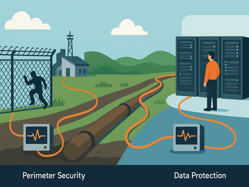
Types of Fiber Security Systems: Perimeter, Pipeline, and Data Protection

Unlike traditional electronic sensors, fiber optic security systems leverage the unique properties of light traveling through cables to detect disturbances with unmatched precision. These systems are immune to electromagnetic interference, capable of covering long distances, and versatile enough to protect physical, industrial, and digital infrastructures. This article explores the three main types of fiber security systems—perimeter security systems, pipeline security systems, and data protection systems. We’ll examine how each works, its commercial benefits, the industries that rely on them, and how businesses can choose the right fit for their needs.  Understanding Fiber Security Systems At their core, fiber optic security systems rely on a principle called Distributed Acoustic Sensing (DAS) or similar technologies. Light pulses travel down the fiber cable, and when vibrations, temperature shifts, or physical disturbances occur, the backscattered light pattern changes. These subtle changes are analyzed in real time by monitoring equipment, which can pinpoint the location and nature of the disturbance. The benefits of this approach are clear: High Sensitivity: Able to detect footsteps, tampering, or even leaks in buried pipelines. Long-Distance Monitoring: One fiber optic line can oversee distances of tens to hundreds of kilometers. Scalability: Easily adapted for small perimeters or nationwide networks. Durability: Fiber optic cables are resistant to electromagnetic interference and environmental conditions. With this foundation in mind, let’s dive into the three major applications. Perimeter Security Systems Definition and Purpose Fiber optic perimeter security systems are designed to safeguard physical boundaries. Instead of relying on traditional sensors like motion detectors or cameras, these systems use buried or fence-mounted fiber optic cables to detect intrusions in real time. How It Works When an intruder climbs a fence, digs under a barrier, or tampers with a restricted boundary, the resulting vibration causes tiny disturbances in the fiber cable. The system translates these disturbances into alerts, accurately identifying the intrusion point. Commercial Applications Airports & Seaports: Protect runways, terminals, and cargo areas. Military Bases: Provide high-security boundary protection. Energy Plants: Safeguard nuclear, solar, and wind energy sites. Data Centers: Safeguard sensitive facilities from unauthorized entry. Advantages Real-time detection with precise location accuracy. Minimal maintenance once installed. Incorporation with surveillance cameras, access control systems, and alarms. Reduced false alarms compared to traditional motion sensors. Challenges Environmental sensitivity (wind, heavy rain, and wildlife can trigger signals). Higher upfront installation cost compared to conventional security fencing. Pipeline Security Systems Definition and Purpose Pipeline networks carry oil, gas, water, and critical utilities across continents. Any leak, theft attempt, or sabotage can cause catastrophic financial and environmental damage. Fiber optic pipeline security systems monitor these networks around the clock. How It Works Fiber optic cables utilize DAS (Distributed Acoustic Sensing) and DTS (Distributed Temperature Sensing) to detect vibrations caused by tampering, leaks, or excavation near the pipeline. They can also sense temperature changes that indicate fluid leakage. Commercial Applications Oil & Gas Companies: Protect pipelines from theft and sabotage. Water Utilities: Monitor for leaks and unauthorized access. Mining Operations: Ensure slurry or chemical pipelines remain intact. Telecom Companies: Safeguard long-distance fiber optic communication lines. Advantages Real-time alerts over hundreds of kilometers. Reduces downtime and financial losses by detecting issues early. Minimizes environmental risks from leaks. Supports compliance with safety and environmental regulations. Challenges Interpreting vast amounts of sensor data requires advanced analytics. Installation requires a considerable initial investment. Needs to be integrated with monitoring centers for quick response. Data Protection Systems Definition and Purpose In the digital age, securing information is as critical as securing physical infrastructure. Fiber optic data protection systems prevent unauthorized tapping or interference with high-value communication networks. How It Works When hackers or malicious actors attempt to bend, tap, or interfere with a fiber optic cable, the system detects changes in the signal pattern. The monitoring equipment instantly raises an alert, pinpointing the attempted breach. Commercial Applications Financial Institutions: Protect banking transactions and customer data. Government Agencies: Safeguard confidential communications. Telecom Providers: Ensure secure data transmission across backbone networks. Corporate Enterprises: Protect intellectual property and customer records. Advantages Prevents covert data tapping or eavesdropping. Ensures compliance with cybersecurity regulations. Protects customer trust and brand reputation. Integrates with broader IT security frameworks. Challenges Requires collaboration with IT departments for full integration. Can produce false positives if not calibrated correctly. Initial costs may be high, especially for retrofitting older networks. Comparative Analysis To better understand the strengths of each fiber security system, the table below summarizes the differences: Feature / Factor Perimeter Security Pipeline Security Data Protection Primary Function Detect physical intrusions Monitor leaks/tampering Prevent data tapping Industries Served Airports, energy, defense Oil & gas, utilities, mining Finance, government, telecom Detection Technology Vibration sensing DAS & DTS Signal integrity monitoring Strengths Accurate location alerts Long-distance monitoring Cyber-physical data protection Challenges Environmental sensitivity High setup cost, analytics Integration with IT systems Scalability Medium to High Very High High This comparison highlights how each system serves unique security goals but together forms a complete defense strategy. Future Trends in Fiber Security Systems The demand for fiber optic security solutions continues to grow as industries modernize and threats evolve. Several major trends are: Artificial Intelligence alongside Machine Learning Smarter analytics to differentiate between real threats and harmless disturbances. Reduced false alarms through automated learning. IoT and Cloud Integration Real-time monitoring dashboards are accessible worldwide. Seamless integration with cloud-based data analytics platforms. Hybrid Security Solutions Combining fiber optics with cameras, drones, and radar for layered protection. Holistic security ecosystems that cover physical and digital threats simultaneously. Cost Reduction and Wider Adoption As technology matures, costs are expected to decrease, making fiber security accessible to medium-sized businesses, not just large enterprises. Organizations have transformed their protection methods for vital assets through the use of fiber security systems. Perimeter systems shield physical boundaries, pipeline systems safeguard vital infrastructure, and data protection systems ensure digital integrity. Each type has unique strengths and applications, but together they form a powerful, integrated security framework.

Fibre Optic Detector vs. Vibration Sensor
Blogs

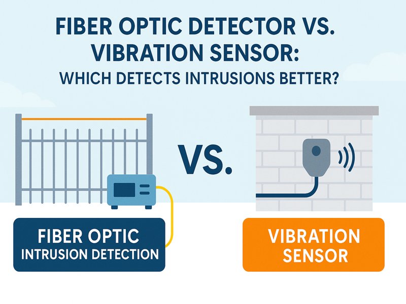
Fibre Optic Detector vs. Vibration Sensor: Which Detects Intrusions Better?

Perimeter security lives and dies on one metric: detect real intrusions quickly without drowning operators in nuisance alarms. Two of the most widely deployed technologies for fence lines, buried perimeters, and walls are fibre-optic detectors and vibration sensors. Both listen for physical disturbances; they just do it in very different ways. This guide compares how they work, what they detect best, where they struggle, and how to choose (or combine) them for your site. Best overall for long, complex perimeters: fibre-optic systems (especially distributed acoustic sensing and interferometric solutions), thanks to kilometre-scale coverage, precise location, and no field electronics. Best for short runs, gates, and targeted retrofits: conventional vibration sensors (MEMS/piezo on the fence or ground) for lower upfront cost and simple, localised deployment. Best outcome for high-risk sites: a hybrid—fibre for continuous detection and geolocation, vibration sensors for special structures (gates, turnstiles), or to add a second technology for alarm correlation. How the technologies work Fibre-optic intrusion detection A single strand of fibre becomes the sensor. A controller (“interrogator”) injects light and analyses the backscatter or interference pattern along the cable. Disturbances—climb, cut, digging, footsteps—modulate the light, which the system maps to distance along the fibre. Two common approaches: Distributed Acoustic Sensing (DAS): measures backscattered light continuously, offering detection and meter-level location over kilometres. Interferometric (e.g., Mach-Zehnder): highly sensitive to vibrations/strain at defined loops or segments, often used fence-mounted or buried. Because the fibre is passive, nothing live sits in the field: no power, no electronics, no radios. The interrogator stays in a secure cabinet or control room. Vibration sensors These are point sensors mounted on a fence, post, wall, or buried shallowly in soil. They use accelerometers (MEMS), piezoelectric elements, or geophones to measure motion. Each sensor covers a local area; a controller aggregates alarms from many nodes. Units may be wired (daisy-chained power/data) or wireless (battery powered, RF mesh). Sensitivity, thresholds, and classification run in the sensor, a nearby module, or a central panel. What each detects best Threat type Fibre-optic detectors Vibration sensors Fence climb/cut/lift Excellent; continuous sensing along the run with precise location Excellent locally; coverage depends on sensor spacing and mounting Buried dig/tunnel Strong with buried fibre; sensitivity extends several meters from the trench Possible with buried geophones; careful array design needed Footsteps on approach Good with DAS on suitable ground and sensitivity tuning Good with ground sensors; range limited to array geometry Gate activity Good, but gates often need special loops or slack management Very good; dedicated sensors on the gate leaf/frame Multiple simultaneous events Very good; one fibre covers many zones with separate locations Good; each node reports independently but needs more wiring Precise geolocation Native; metre-level along fibre By zone only, unless dense sensor spacing Detection performance, false alarms, and classification Probability of Detection (Pd) and Nuisance Alarm Rate (NAR) are the core KPIs. In practice, both technologies achieve high Pd when installed and tuned correctly. Where they diverge is context: Fibre-optic systems typically excel at localising events (e.g., “climb at 2,347 m on the south fence”) so operators can slew PTZ cameras quickly, dispatch correctly, and review patterns over time. Advanced analytics distinguish wind-induced fence swaying from cutting or ladder application by analysing frequency content, persistence, and multi-point correlation along the cable. Vibration sensors can be exquisitely sensitive at a point but may produce more nuisance alarms if spacing is wide, tie-downs are inconsistent, or fence fabric resonates under wind. Modern MEMS units with onboard classification and adaptive thresholds help a lot, but coverage uniformity across long runs remains an installation challenge. Common nuisance-alarm sources for both: wind-driven fence motion, loose panels, vegetation, heavy nearby machinery, wildlife, hail/rain bursts, and maintenance activities. Fibre systems mitigate with pattern-based analytics across distance; vibration networks mitigate with per-sensor tuning and mechanical isolation. Environmental robustness Electromagnetic immunity: Fibre is dielectric—no risk of EMI/RFI coupling, and no ground loops. Conventional sensors and long copper runs can be susceptible (mitigated by shielding and proper earthing). Lightning & surge: Fibre has no field power, reducing surge risk. Metallic fences will still move during strikes, which either system will sense as an event; the difference is that fibre won’t carry surge into electronics along the fence. Temperature, UV, corrosion: Outdoor-rated fibre and stainless/UV-stable ties are reliable over decades if bending radius and strain limits are respected. Vibration sensors live outdoors permanently; IP-rated housings and cable glands are critical. Wireless nodes face battery and gasket ageing. Installation and commissioning Fibre-optic Pros: One continuous cable covers kilometres; minimal field hardware; fast to segment into software “zones”; excellent retrofit on existing fences; trench-based install for buried detection. Cons: Requires attention to cable routing, slack loops at gates/expansion joints, bend radius, and protected splicing. Buried fibre means civil work; fence-top fibre must be consistently tied and tensioned. Vibration sensors Pros: Simple for short runs, gates, doors, and special structures; can be wireless where cabling is hard; per-sensor tuning allows local optimisation. Cons: For long perimeters, the sensor count rises quickly. Daisy-chained wiring or battery maintenance becomes significant. Consistency of mounting and tie-down strongly impacts performance. Operations & maintenance (O&M) Fibre-optic: With no field electronics, there’s little to maintain beyond periodic visual checks (ties intact, no fence damage), interrogator firmware updates, and re-tuning after structural changes. Fibre breaks are rare but are easy to localise precisely when they occur. Vibration sensors: Expect battery replacements (wireless), connector inspections, corrosion checks, and occasional recalibration after severe weather or repairs. Stocking spare nodes reduces downtime. Integration, alarm handling, and cybersecurity Both technologies integrate with PSIM/VMS, access control, and alarm panels via dry contacts, TCP/IP, SNMP, REST, or event streams. Practical differences: Fibre-optic: Supplies precise coordinates; VMS can auto-slew PTZ cameras and display event pins on GIS maps. Analytics metadata (cut vs. climb vs. dig) is rich. One headend simplifies network hardening. Vibration sensors: Offer per-zone alarms; some provide rich metadata and health status. If many nodes are IP-enabled, harden the network: VLANs, certificate management, and patching across many endpoints. Cost of ownership (indicative) Upfront hardware

Foids Maintenance Tips
Blogs

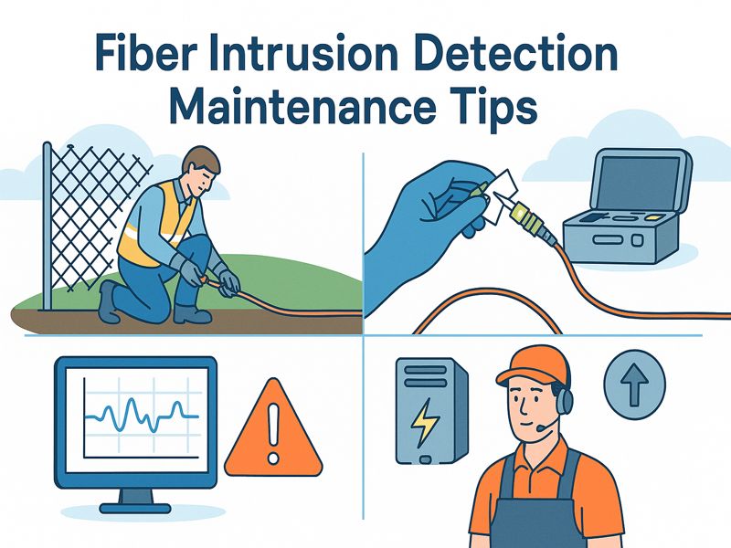
Fiber Intrusion Detection Maintenance Tips for Reliable Performance

We help customers maintain optimal performance of their fiber-optic intrusion detection systems by exploring practical, business-focused maintenance tips. From routine inspections to environmental considerations, we’ll outline best practices for protecting your infrastructure and reputation. The Importance of Maintenance in Fiber Intrusion Detection Unlike conventional sensors, fiber optic systems rely on highly sensitive light transmission to detect vibrations, pressure, and intrusions along the cable. While the fiber itself is passive and highly durable, the performance of the system depends on connectors, enclosures, splicing quality, and software calibration. Neglecting maintenance can lead to false alarms, signal losses, or worse—undetected breaches. For industries where downtime or compromised security translates directly into financial loss, maintenance is not optional. It’s a business continuity strategy. Routine Inspection of Fiber Optic Cables The backbone of intrusion detection is the fiber cable. Even though fiber has a life expectancy exceeding 25 years, regular inspections are essential. Checklist for inspections: Visual survey: Look for visible damage, bends tighter than the minimum radius, or exposed cable. Connector check: Ensure all connectors are dust-free, capped, and firmly secured. Splice protection: Confirm that splices are enclosed properly to avoid moisture intrusion. Mechanical stress points: Inspect areas near gates, fences, or roads where external forces are likely. Routine visual inspections reduce the likelihood of undetected degradation and allow proactive interventions before system alarms are triggered unnecessarily. Cleaning Fiber Connectors and Hardware Dust, dirt, or oil on connectors can lead to significant signal attenuation. Even a microscopic particle can block light transmission and cause false positives. Best practices for cleaning: Use lint-free wipes or pre-moistened fiber cleaning sticks. Never use your bare hands to contact the fiber end. Follow the “inspect-clean-inspect” protocol using a fiber scope. Store unused connectors with protective caps. A disciplined cleaning routine ensures the sensing accuracy remains uncompromised over time. Monitoring Software Calibration Advanced algorithms are used by fiber intrusion detection systems to distinguish between real threats and background noise from things like wind, rain, and wildlife. Over time, system settings may drift due to environmental changes or cable expansions. Maintenance recommendation: Schedule quarterly calibration tests. Simulate intrusion attempts (climbing, cutting, digging) at various locations. Adjust sensitivity settings to balance detection accuracy with false alarm reduction. Regular calibration guarantees that the system adapts to evolving site conditions without sacrificing reliability. Power Supply and Backup Systems Like all electronic security systems, fiber intrusion detection relies on continuous power. Power interruptions not only cause downtime but also may reset system parameters. Key maintenance tasks: Test backup batteries monthly. Inspect UPS (uninterruptible power supply) units for capacity loss. Verify generator integration if used in critical facilities. Document runtime capabilities under full load. A robust power maintenance program ensures the system stays online during unexpected outages. Environmental Considerations Fiber systems are designed to withstand harsh environments, but extreme weather or site conditions require extra care. Temperature fluctuations: Ensure cables are rated for local temperature extremes to prevent cracking. Moisture protection: Verify sealants and enclosures in flood-prone or coastal areas. Rodent control: Install protective conduits in areas where wildlife may chew cables. UV exposure: Check for UV-resistant sheathing in outdoor applications. Accounting for these factors extends the life of the infrastructure and prevents avoidable failures. Software and Firmware Updates Intrusion detection systems increasingly integrate with AI-based analytics and command-and-control platforms. Outdated software can create vulnerabilities not just in performance but also in cybersecurity. Maintenance protocol: Schedule semi-annual software and firmware updates. Test compatibility with integrated systems (CCTV, access control). Verify new updates don’t alter detection zones or reset parameters. Document version histories for compliance audits. Staying current with updates maximizes system capabilities and strengthens cybersecurity resilience. Alarm Verification and Response Testing The ability of a system to trigger reliable alarms is a measure of its effectiveness. Maintenance must include regular verification of alarm outputs and the response chain. Alarm testing: Conduct routine simulations and verify that alarms reach the monitoring station. Response chain audit: Ensure security personnel receive, understand, and act on alerts. Integration check: Confirm alarms trigger secondary systems like lights, sirens, or cameras. Testing response readiness ensures the fiber system functions not only as a sensor but as part of a wider security ecosystem. Documentation and Maintenance Logs Documenting every inspection, test, and repair is critical for performance tracking, warranty claims, and compliance. What to include in logs: Inspection dates and results. Calibration and test reports. Repair or replacement records. Technician signatures and certifications. Digital maintenance logs integrated with asset management software provide traceability and data for predictive maintenance planning. Training Security and Maintenance Personnel Even the most advanced fiber optic system can underperform if staff are not properly trained. Training should cover: Proper handling of fiber cables and connectors. Alarm verification procedures. Cleaning protocols and calibration basics. Recognizing environmental vs. genuine intrusion alerts. Investing in training reduces human error, extends system life, and ensures rapid troubleshooting. Partnering with Professional Service Providers Many organizations lack in-house fiber expertise. Partnering with certified service providers ensures maintenance aligns with industry best practices. Advantages of outsourcing maintenance: Access to specialized test equipment (OTDR, power meters). Predictive diagnostics based on fiber signal analysis. Rapid response teams for emergency repairs. Compliance with manufacturer service standards. Choosing a reliable partner ensures continuous, professional oversight without overburdening internal teams. Predictive and Preventive Maintenance The trend in modern security infrastructure is shifting from reactive to predictive maintenance. Fiber intrusion detection is no exception. Strategies include: Finding weak places before they fail is possible with OTDR (Optical Time-Domain Reflectometer) instruments. Leveraging AI-based monitoring platforms for early warning of degradation. Scheduling preventive component replacements at recommended intervals. Predictive maintenance lowers long-term costs, minimizes downtime, and ensures uninterrupted protection. Cost of Neglect vs. Value of Maintenance Presenting maintenance as an investment rather than an expense is necessary from a business perspective. Consequences of neglect: Expensive emergency repairs. False alarms leading to operational disruption. Missed detections risking theft, sabotage, or liability. Benefits of disciplined maintenance: Maximized system lifespan. Reduced total cost of ownership (TCO). Enhanced reliability and client confidence. Higher ROI on security investments.

FOIDS Common Mistakes
Blogs

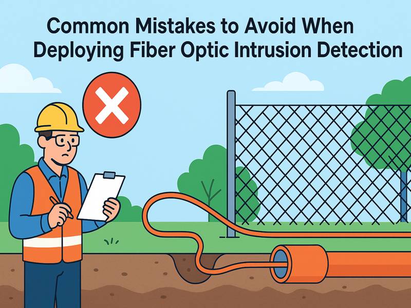
Common Mistakes to Avoid When Deploying Fiber Optic Intrusion Detection

FOIDS offer unparalleled sensitivity. Nonetheless, like any sophisticated security technology, its effectiveness relies on both the equipment and its deployment. Missteps during planning, installation, or integration can undermine performance, increase costs, or create blind spots in the system. Underestimating Site Assessment Needs One of the most frequent errors is failing to conduct a thorough site survey before installation. While fiber optic sensors are very sensitive, they need to be customized for the specific terrain, structures, and environmental conditions of the site where they will be deployed. Mistake: Installing sensors without considering soil composition, fence condition, vibration sources, or local wildlife activity. Impact: Leads to excessive false alarms or undetected breaches. Solution: Conduct a detailed risk and site assessment to identify noise sources (e.g., nearby highways, construction sites) and natural obstacles. Use this information to calibrate sensor placement and sensitivity. Choosing the Wrong Fiber Type Not all optical fibers are created equal. Single-mode and multi-mode fibers behave differently under strain and vibration, and the wrong choice can compromise detection performance. Mistake: Using general-purpose communication fiber instead of fiber designed for sensing applications. Impact: Reduced detection accuracy and shortened monitoring range. Solution: Select sensor-grade fiber designed for distributed acoustic sensing (DAS) or specific FOIDS applications, ensuring the fiber is ruggedized for environmental exposure. Overlooking Proper Cable Installation Techniques Improper cable laying and routing is another pitfall. Fiber must be installed in ways that ensure consistent sensitivity along its length. Mistake: Tight bends, uneven burial depths, or poorly secured cables on fences. Impact: Weak points in detection, reduced longevity, or mechanical damage. Solution: Follow manufacturer guidelines for bend radius, burial depth, and securing methods. Use protective conduits in high-risk areas to prevent accidental cuts. Neglecting Calibration and Tuning Even with high-quality equipment, fiber optic intrusion detection systems require careful calibration to balance detection sensitivity and noise rejection. Mistake: Assuming factory settings are adequate for all environments. Impact: High rates of false alarms or missed intrusion attempts. Solution: Perform site-specific calibration, adjusting thresholds and algorithms based on real-world data collected during testing. Periodically recalibrate to adapt to seasonal or environmental changes. Failing to Plan for Integration with Existing Systems Fiber optic intrusion detection rarely operates in isolation. It is most effective when integrated with other security platforms such as CCTV, access control, or command-and-control software. Mistake: Deploying FOIDS as a stand-alone system without integration. Impact: Delayed response to intrusions and inefficient use of alarms. Solution: Integrate FOIDS with video surveillance and alarm management platforms for rapid verification and coordinated responses. 6. Ignoring Environmental Factors Environmental conditions—rain, snow, wind, or seismic activity—can cause significant background noise. Failing to account for them leads to excessive false positives. Mistake: Not testing the system under varying weather conditions. Impact: Operators lose confidence in the system due to frequent nuisance alarms. Solution: Deploy advanced signal processing and weather-resistant fiber housings. Schedule testing during different seasons to ensure system stability. Insufficient power and network redundancy The infrastructure that supports it determines the reliability of a FOIDS. Power failures or network outages can render the system useless at critical moments. Mistake: Relying on single-source power and non-redundant communication paths. Impact: System downtime, leaving assets unprotected. Solution: Use redundant power supplies (UPS, solar backup) and failover communication channels. Ensure the network design includes redundancy. Poor Alarm Management Alarms are only effective if they lead to timely, accurate responses. Too many false alarms or poorly configured notifications overwhelm operators. Mistake: Setting alarm thresholds too low or not categorizing alerts. Impact: Alarm fatigue, with critical events potentially ignored. Solution: Implement tiered alarm management, prioritizing alerts by severity. Train staff to distinguish between nuisance alarms and genuine threats. Overlooking Maintenance and Periodic Testing Some organizations treat FOIDS as “set it and forget it” systems. But cables degrade, environments change, and calibration drifts. Mistake: Skipping routine inspections, firmware updates, and recalibration. Impact: System gradually loses accuracy and reliability. Solution: Establish a maintenance schedule that includes periodic inspections, performance tests, and updates to both hardware and software. Lack of Operator Training Even the most advanced FOIDS cannot compensate for poorly trained personnel. It is essential for operators to grasp how to make sense of data and react accordingly. Mistake: Providing minimal or one-time training during installation. Impact: Misinterpretation of alarms, delayed responses, and underutilization of system features. Solution: Provide continuous training programs, simulations, and refresher courses to ensure staff remain proficient in system use and troubleshooting. Insufficient Cybersecurity Safeguards Modern FOIDS often rely on IP-based communication, making them vulnerable to cyberattacks if not properly secured. Mistake: Overlooking cybersecurity protections for FOIDS control units and software. Impact: Hackers could disable or manipulate the system, creating false security. Solution: Use encrypted communication, strong authentication, and regular vulnerability testing. Follow best practices for securing industrial control systems. Overpromising Capabilities Marketing materials may suggest FOIDS can detect every disturbance flawlessly, but real-world conditions are more complex. Mistake: Overestimating system performance or making unrealistic promises to stakeholders. Impact: Disappointment and loss of trust when the system doesn’t meet inflated expectations. Solution: Set realistic expectations during planning. Clearly communicate system strengths and limitations to management and operators. Neglecting to Plan for Scalability Organizations frequently concentrate on present requirements, overlooking the potential for future growth. Adding more zones or extending coverage later can be costly if not planned from the start. Mistake: Designing a system without modularity or expansion capacity. Impact: High costs and complexity when scaling up. Solution: Choose systems that support modular expansion and design initial deployments with future growth in mind. Overlooking Regulatory Compliance Critical infrastructure often has regulatory requirements regarding security systems. Mistake: Deploying FOIDS without confirming compliance with local or international standards. Impact: Legal liability and costly retrofits. Solution: Ensure system design and deployment meet relevant standards (e.g., ISO, IEC, or government-specific regulations). Skipping Independent Validation Lastly, many organizations rely solely on vendor claims without independent validation of performance. Mistake: Accepting vendor specifications at face value without third-party testing. Impact: Potential mismatches between promised and actual performance. Solution: Conduct independent performance evaluations or engage third-party security consultants to

Fence Alarm System
Blogs

Top 10 Electric Fence Manufacturers in the World

The electric fence industry has evolved into a dynamic sector, fulfilling a dual role: livestock management in the agricultural sector and critical infrastructure security in the security industry. With the growing global demand for perimeter protection—whether for animal control or deterring intruders—selecting a trustworthy manufacturer is more important than ever. This article profiles ten influential electric fence manufacturers worldwide, showcasing their strengths, global reach, and technological offerings. Gallagher Headquarters: Hamilton, New Zealand Overview: Founded in 1938, Gallagher is one of the earliest pioneers in electric fencing. The company manufactures energizers, portable kits, and accessories for farms and security installations worldwide. With products tested in extreme climates, Gallagher is trusted by both small farms and large estates across Oceania, North America, and Europe. They also invest in smart fencing systems that integrate with livestock monitoring technologies. Key Strengths: Durable energizers suitable for harsh environments Wide portfolio covering agriculture and security Strong global dealer and service network Shanghai Gato Information Technology Co., Ltd. Headquarters: Shanghai, China Overview: Shanghai Gato is a modern leader in electric fencing and perimeter intrusion detection. Unlike traditional livestock fencing companies, Gato focuses heavily on advanced security applications. Their portfolio includes pulse electric fences, tensile fences, buried sensors, fiber optic detection, and laser beam systems, serving critical infrastructure, borders, and high-security facilities. With more than 150 patents, ISO/CE certifications, and projects completed in 30+ countries, Gato is setting a new benchmark for intelligent, adaptive perimeter security. Key Strengths: Advanced smart security and intrusion detection solutions Over 150 patents and global certifications 300,000+ successful projects worldwide Woodstream Corporation (Zareba Systems) Headquarters: Pennsylvania, USA Overview: Woodstream’s Zareba® Systems brand is the largest electric fence manufacturer in North America. Their products are popular among DIY enthusiasts, hobby farmers, and rural households thanks to easy-to-install fence kits. Zareba offers energizers, insulators, posts, reels, and conductors, distributed widely through farm stores and major retailers. Their 75+ years of expertise ensure durability and accessibility in every product line. Key Strengths: North America’s largest electric fence supplier DIY-friendly systems with wide retail reach Full range of accessories for flexible installation Parker McCrory (Parmak) Headquarters: Kansas City, Missouri, USA Overview: Operating since 1937, Parker McCrory’s Parmak brand is the world’s oldest producer of electric fence chargers. They specialize in rugged American-made energizers, including solar-powered and battery models. Parmak products are particularly respected for their reliability on remote ranches where consistent power is critical. Their heritage makes them a preferred brand among traditional farmers in the U.S. Key Strengths: Over 85 years of industry leadership Robust solar and battery-powered energizers Trusted American-made quality Nemtek Headquarters: Johannesburg, South Africa Overview: Nemtek designs and manufactures electric fencing products for both agricultural and high-security applications. Their catalog includes energizers, wires, insulators, monitoring devices, and posts. Nemtek is especially recognized for security-grade fencing, used in industrial and government installations as well as farms. With 30+ years in the business, they export extensively to Africa, Asia, and global markets. Key Strengths: Dual focus: farming and high-security perimeters Advanced energizer and monitoring solutions Strong distribution network in emerging markets JVA Technologies Headquarters: Brisbane, Australia & Johannesburg, South Africa Overview: JVA Technologies produces energizers and monitoring systems for both livestock control and high-security installations. Their products are widely used in farms across Australia and Africa, and in sensitive perimeter applications such as prisons and military sites. JVA emphasizes remote management and smart integration, allowing users to monitor fences via connected platforms. Key Strengths: High-security fencing solutions for critical sites Remote management and smart monitoring features Active presence in Australasia and Africa LACME Headquarters: La Flèche, France Overview: LACME is one of Europe’s leading electric fence manufacturers, supplying energizers, conductors, and accessories for agriculture and equestrian use. Their proprietary HTE/HVE technology ensures consistent energy distribution across changing fence conditions. With more than six decades of experience, LACME is highly regarded in the EU market for balancing innovation with animal safety. Key Strengths: Proprietary energy management technology Strong focus on equine and EU farms Broad product range from small to large systems horizont group Headquarters: Korbach, Germany Overview: Horizont Group operates through its Animal Care division to supply modern electric fencing systems for all major livestock species. With more than 75 years of experience, they produce energizers, posts, conductors, and portable fencing systems. Their European presence is complemented by exports worldwide, making them a reliable partner for farmers needing compliance with strict EU standards. Key Strengths: Large-scale catalog covering multiple livestock types Over 75 years of engineering expertise Strong EU compliance and distribution network AKO-Agrartechnik (Kerbl Group) Headquarters: Buchbach, Germany Overview: AKO-Agrartechnik, under the Kerbl Group, is one of Europe’s largest electric fence producers. The company has quintupled its production since 2000, offering smart energizers, solar units, and accessories. AKO’s “Smart” series of energizers provide cloud connectivity and GPS integration, appealing to farmers seeking data-driven pasture management. Key Strengths: Smart energizers with cloud/GPS connectivity Full catalog of conductors, testers, and posts Rapid growth in EU and international markets Datamars Livestock (Speedrite, Stafix, PEL, Patriot) Headquarters: Lugano, Switzerland Overview: Datamars owns several of the world’s best-known electric fence brands: Speedrite, Stafix, PEL, and Patriot. This diverse portfolio allows them to serve hobby farmers, mid-size ranchers, and industrial-scale livestock operators. Their energizers come in mains, battery, and solar options, while their smart fence management tools help farmers track performance. Datamars has a strong presence in Europe, North America, and Oceania. Key Strengths: Multi-brand coverage across global markets Emphasis on smart and digital pasture management Trusted by both commercial and small-scale farmers Comparison Table: At a Glance Manufacturer Country Primary Focus Special Strengths Gallagher New Zealand Agriculture & security Climate-tested energizers, global reach Shanghai Gato Information Technology China Security & smart fencing Fiber optic, laser, pulse electric systems Datamars (Speedrite, etc.) Switzerland Agriculture Multi-brand, smart monitoring Woodstream (Zareba) USA Agriculture (DIY) Strong retail presence, easy installation Parker McCrory (Parmak) USA Agriculture Solar/battery energizer heritage Nemtek South Africa Agriculture & security Security-grade fencing solutions JVA Technologies Australia/SA Agriculture & security Remote monitoring, prison/military use LACME France Agriculture & equine

Leave Your Message