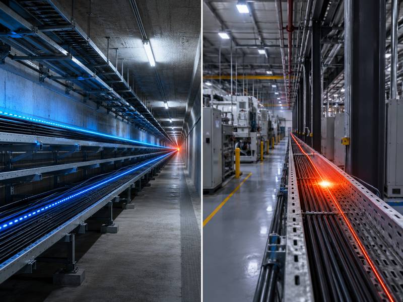
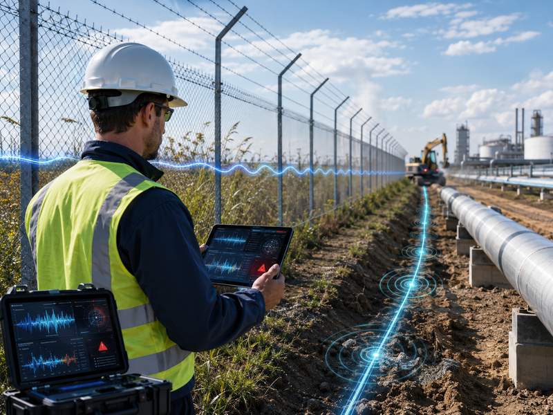
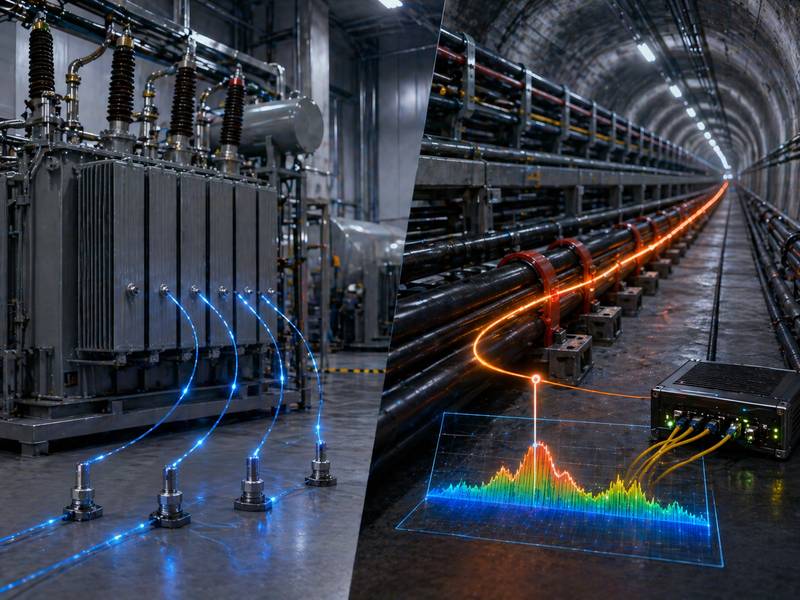
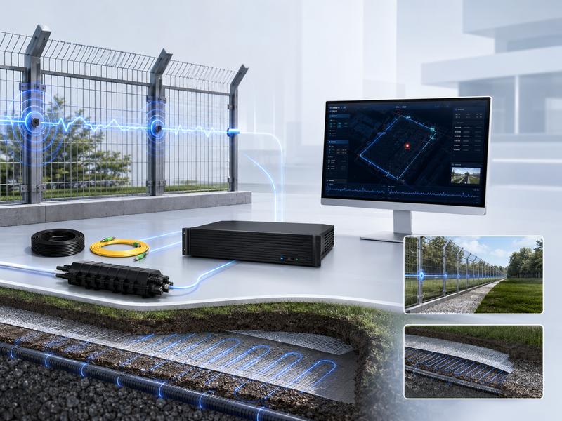
The F7 DAS AI vibration fiber optic system provides continuous perimeter intrusion detection for fences, walls, buried zones, industrial sites, airports, warehouses, and other high-security areas. It detects vibrations from climbing, cutting, digging, or knocking, then analyzes the signal and sends alarms.
Correct installation and commissioning help improve detection accuracy, reduce false alarms, and ensure stable long-term operation. This guide covers accessories, fence-mounted and buried installation, host wiring, configuration, testing, troubleshooting, and maintenance.
Standard Components Before Installation
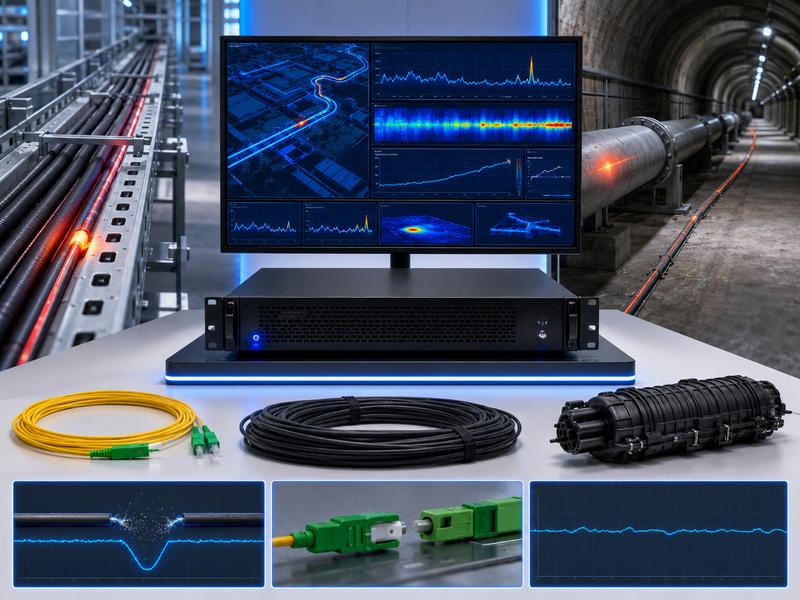
Before starting installation, confirm that all required components are ready. The system accessories should be dedicated components for the F7 Distributed Acoustic Sensing AI vibration fiber optic system. Avoid replacing them with unapproved materials, because unsuitable fiber, splice boxes, or connectors may affect signal quality and system reliability.
| Component | Function | Installation Note |
| F7 host | Main detection and analysis unit | Installed in the equipment room or secure control cabinet |
| Communication optical cable | Used for signal transmission | Keep the cable protected and avoid sharp bending |
| Fiber jumper | Connects the host and optical interface | Match the correct connector type before tightening |
| Fiber splice box | Protects fusion splice points and reserved fiber | Keep waterproof, sealed, and easy to inspect |
Before installation, check whether the host, communication fiber cable, optical jumper, and splice box are complete. Also prepare basic installation tools, including cable ties, fiber fusion splicer, optical power meter, network cable, laptop, power supply, protective conduit, warning labels, and waterproof accessories.
Two Installation Methods: Fence-Mounted and Buried
The F7 DAS(Distributed Acoustic Sensing) AI vibration fiber optic system supports two common installation methods: fence-mounted installation and buried installation. The right choice depends on site conditions, perimeter structure, concealment needs, construction cost, and security level.
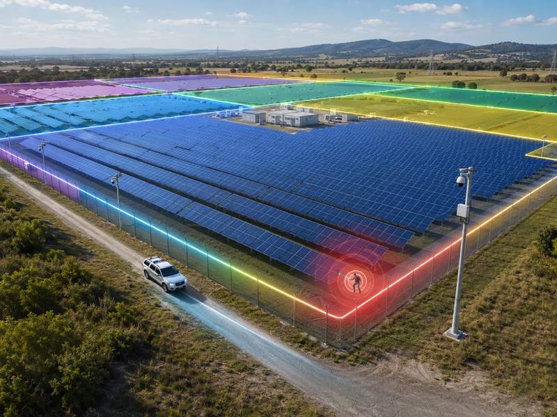
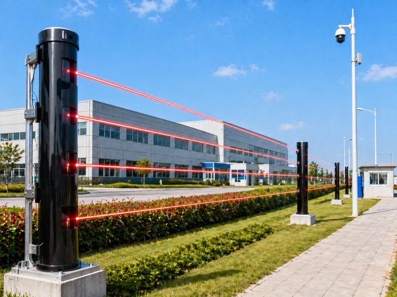
Fence-Mounted Installation
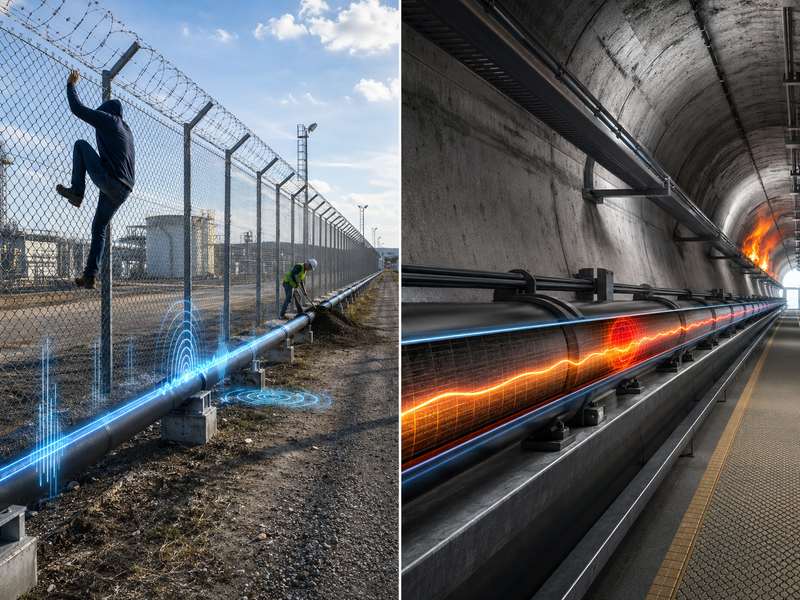
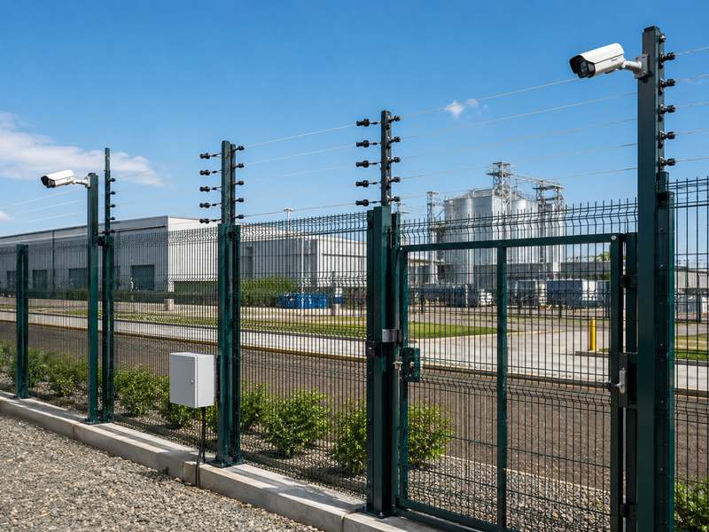
Fence-mounted installation is suitable for metal mesh fences, iron fences, welded fences, wall-top fences, and other perimeter structures where vibration can be transferred to the sensing cable. Installing and maintaining this method is simpler. It is commonly used for factories, solar farms, logistics parks, substations, oil and gas sites, and general industrial perimeters.
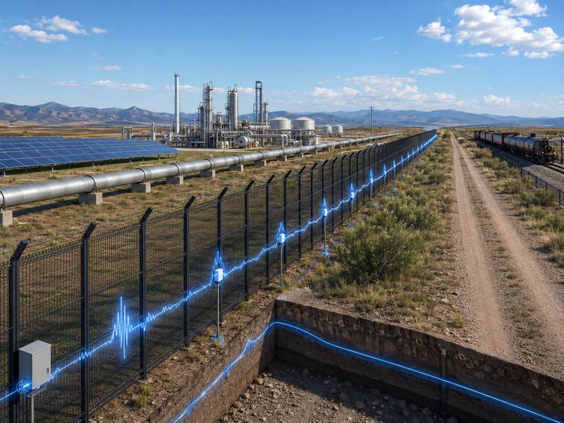
Buried Installation
Buried installation is suitable for hidden perimeter protection. The optical fiber cable is placed underground with protective layers, making it difficult to find or damage. This method is useful for high-security sites, open land boundaries, airport perimeters, military areas, and locations where visible devices are not preferred.
| Installation Method | Best For | Advantages | Key Consideration |
| Fence-mounted installation | Mesh fence, iron fence, wall fence | Easy construction, easy maintenance, lower cost | The cable must be firmly fixed |
| Buried installation | Hidden perimeter protection | Concealed, anti-digging, harder to damage | Requires trenching and layered construction |
Fence-Mounted Installation Guide
For fence-mounted installation, the sensing fiber should be fixed along the fence structure. The cable should follow the perimeter route continuously and remain close enough to the fence body to receive vibration signals.
The image shows two main routing methods: straight-line installation and wave-type installation.
Straight-Line Installation
Straight-line installation is simple and suitable for standard fences with a stable structure. The optical fiber cable is fixed along the fence line using cable ties. This method is easy to install and helps keep the routing clean.
Main advantages include:
- Simple routing
- Fast installation
- Easy inspection
- Suitable for long and regular perimeter sections
Wave-Type Installation
Wave-type installation increases contact coverage and can improve detection sensitivity. The cable is arranged in a wave pattern along the fence, allowing the system to capture vibration signals from more fence areas.
Main advantages include:
- Better sensitivity
- Wider vibration coverage
- Suitable for higher-risk sections
- Better performance on complex fence structures
For both methods, cable ties should be used to fix the optical cable securely. The recommended fixing distance is usually 15–30 cm. This helps prevent loose cable movement caused by wind, rain, or long-term vibration. A loose cable may increase background noise and cause unstable alarm performance.
Key Tips for Fence Installation
During fence installation, pay attention to cable spacing, reserved fiber, fusion splice loss, and connector protection.
| Installation Item | Recommended Requirement | Purpose |
| Cable tie spacing | Around 15–30 cm | Prevent loose cable and unstable vibration signals |
| Reserved fiber length | More than 50 m at terminal section | Supports future maintenance and adjustment |
| Fusion splice loss | Less than 0.3 dB | Maintains stable optical signal quality |
| Cable routing | Smooth and continuous | Avoids signal interruption and cable damage |
| Connector protection | Dust cap first, then tighten the connector | Prevents optical interface contamination |
The fiber end should reserve enough length and be placed inside the splice box. The reserved cable should not be sharply bent. Always follow the minimum bending radius required for the selected optical cable. Excessive bending can damage the fiber core and reduce optical signal quality.
Fusion splice quality is also important. If the splice loss is too high, the system may show a weak signal, unstable detection, or no optical signal. Keep fusion splice loss below the required value and protect the splice point inside the fiber splice box.
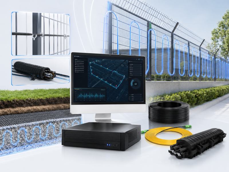
Buried Installation Guide
Buried installation provides hidden perimeter protection. The construction method shown in the image uses layered protection from top to bottom:
- Soil cover layer
- Geotextile layer
- Vibration optical cable
- Plastic grid layer
This layered design helps hide the cable while improving anti-digging performance. The plastic grid can transfer digging or ground disturbance vibration to the sensing cable, while the geotextile helps stabilize the soil layer and protect the cable route.
Buried Installation Process
First, dig the trench along the planned perimeter route. The trench route should follow the security boundary and avoid heavy vehicle pressure zones, drainage channels, and areas with frequent construction activity.
Second, place the bottom protection layer, such as a plastic grid or other approved support material. This layer helps transfer vibration and protects the cable from direct contact with sharp stones or hard soil.
Third, lay the vibration optical cable according to the design route. The cable should be placed smoothly without twisting, sharp bending, or heavy pulling.
Fourth, cover the cable with geotextile and soil. The soil should be compacted properly. The final surface should look natural and should not expose the cable route.
Buried Installation Advantages
Buried installation is more concealed than fence-mounted installation. It can reduce the chance of intentional cable damage and provide better hidden protection against digging, crawling, or crossing attempts. It is especially useful for sites where visible fence sensors are not allowed or where the perimeter appearance must remain clean.
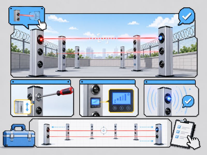
F7 Host Wiring: Connect Each Interface Correctly
The F7 host is the core unit of the system. Correct wiring is essential for system operation. The image highlights one key point: wiring is not complicated, but the connector must match the correct port.
Before connecting the optical fiber jumper, align the notch of the connector with the interface slot. Tighten it carefully after alignment. Do not force the connector into the port, because this may damage the optical interface.
Main Interfaces of the F7 Host
| Interface | Function | Note |
| AC220 power switch | Connects to a 220V AC power supply | Confirm site power stability before startup |
| Power cable interface | Connects the power cable | Ensure reliable grounding and safe wiring |
| Channel 1/2 optical signal input | Optical signal input, FC/APC type | Match the connector direction before tightening |
| 100M/1000M Ethernet interface | Network communication | Usually connect to the network port 1 |
| Output of an intrusion or malfunction alarm | Change the output of the alarm link. | Allows for common, typically closed, and normally open terminals. |
| RS485 bus interface | External address code or linkage module | Used for integration with other devices |
| Local branch interface | Supports hardwired defense zones | Useful for local zone control |
| DC12V output | DC output under 1A | Used only within rated load |
For alarm output, confirm whether the external device requires a normally open or a normally closed signal. Incorrect alarm output wiring may cause failure in linkage devices such as sirens, alarm panels, access control systems, or video surveillance platforms.
System Commissioning: Core Configuration Flow
After physical installation and wiring are complete, the system must be commissioned through the software platform. Commissioning helps the system understand cable length, channel mode, perimeter boundary, defense zones, map layout, network address, and alarm threshold.
Step 1: Network Access and Login
Connect the commissioning computer and the F7 host network port to the same local area network. Open a browser and access the default host IP address, such as 192.168.9.170. Use the administrator account to log in.
Make sure that the host IP and computer IP are in the same network segment throughout this stage. If the page cannot open, check network cable connection, IP settings, firewall restrictions, and browser compatibility.
Step 2: Guided Initialization Setting
Enter the parameter setting guide and complete the initial configuration step by step.
Key tasks include:
- Select working mode and channel
- Obtain or enter optical cable length
- Mark the perimeter boundary
- Click the start point and end point
- Enter actual site position
- Divide defense zones
- Upload the base map
- Draw the electronic fence
- Set the host network address
This step is important because the system needs to match the physical fiber route with the digital map. Accurate boundary marking helps operators quickly locate intrusion points when an alarm occurs.
Threshold Calibration: The Key Step for Stable Detection
Threshold calibration is one of the most important steps in system commissioning. The goal is to balance detection sensitivity and false alarm control.
During calibration, perform field tapping or simulated intrusion tests. Observe the signal value on the platform and compare it with the background noise level. Then set a reasonable alarm threshold for each defense zone.
If the threshold is too low, the system may produce false alarms caused by wind, rain, vehicle vibration, animals, or normal fence shaking. The system might overlook actual incursion events if the threshold is set too high. A practical threshold should be based on real site testing instead of only using default values.
| Threshold Setting Problem | Possible Result | Optimization Method |
| Threshold too low | Frequent false alarms | Increase threshold or enable AI filtering |
| Threshold too high | Missed intrusion alarms | Lower threshold after field testing |
| Same threshold for all zones | Uneven performance | Set thresholds by zone environment |
| No field test | Poor alarm accuracy | Use tapping and simulated intrusion tests |
For complex sites, different defense zones may need different thresholds. For example, a fence section near a road may require stronger filtering than a quiet back-area fence. A buried section near soft soil may also need different settings from a compacted ground section.
Function Configuration Based on Site Needs
After threshold calibration, configure additional functions according to the project requirements.
AI Mode Recognition
Mode recognition can be used to identify or filter common interference patterns such as wind, rain, and environmental vibration. For sites with frequent weather changes, enabling or training recognition models can help reduce false alarms and improve long-term stability.
Shielding Area Configuration
Some areas do not need alarm detection, such as gates, maintenance entrances, or sections with regular vehicle movement. In the shielding area configuration, set these sections as non-alarm zones. This can reduce unnecessary alarms without affecting other protected areas.
Alarm Linkage Configuration
If the F7 system needs to connect with cameras, sirens, alarm panels, or security platforms, configure the alarm output and communication interface correctly. Test each linkage output after configuration to ensure the alarm can trigger external devices normally.
Testing and Verification
After installation and software configuration, conduct full-site testing. Testing should include fence climbing simulation, tapping test, digging simulation for buried sections, cable disturbance test, and alarm output verification.
On the map interface, confirm whether the alarm location is accurate. Also, check whether the alarm output linkage works normally. If the system is connected to CCTV, verify whether the correct camera can be triggered after an alarm.
Testing should not be done only once. It is better to test different perimeter sections, different defense zones, and different intrusion behaviors. This helps confirm whether the system is stable across the whole site.
Common Problems and Quick Troubleshooting
| Problem | Possible Cause | Solution |
| No optical signal | Fiber not connected or poor fusion splice | Check connection and redo fusion splicing |
| Cannot connect to network | IP setting issue or network cable failure | Check IP configuration and replace network cable |
| No alarm output | Wiring error or wrong NO/NC setting | Check wiring and confirm output mode |
| Frequent false alarms | Loose cable, low threshold, strong interference | Tighten cable, adjust threshold, enable filtering |
| Alarm location inaccurate | Cable length or map setting error | Reconfigure cable route and defense zone |
| Weak signal | Connector contamination or excessive splice loss | Clean connector and inspect splice points |
Daily Maintenance Recommendations
Regular maintenance helps keep the F7 distributed acoustic sensing AI vibration fiber optic system stable over time. Site operators should inspect the cable route, host condition, network status, and alarm records regularly.
Recommended maintenance tasks include:
- Check whether the optical cable is loose, moved, or damaged.
- Keep the host clean and well ventilated.
- Inspect splice boxes for water, dust, or physical damage.
- Review alarm logs and identify repeated false alarm sections.
- Perform system detection and calibration every six months.
- Keep installation drawings, wiring records, and configuration files for future maintenance.
For outdoor sites, special attention should be paid after storms, heavy rain, construction work, fence repair, or landscaping activities. These activities may change the cable position or site vibration environment.
The F7 DAS AI vibration fiber optic system provides continuous perimeter intrusion detection for fence-mounted and buried applications. Reliable performance depends on correct installation, wiring, commissioning, and maintenance.
Before installation, check the host, optical cable, fiber jumper, and splice box. Secure cables properly, reserve fiber, control splice loss, and follow layered buried construction when needed.
After installation, complete login, initialization, zone division, map upload, threshold calibration, testing, and maintenance planning to improve detection accuracy, reduce false alarms, and strengthen perimeter protection.