Choose single-ended DTS when the supported measurement method and route conditions allow reliable temperature monitoring from one accessible end; consider double-ended DTS when measurements from both directions provide useful compensation for differential optical loss. The decision depends on the interrogator, fiber arrangement and calibration method. A cable loop by itself does not establish double-ended measurement or guarantee monitoring after a break.
Start with the required measurement quality and physical route, then ask the supplier which configurations the proposed distributed temperature sensing system supports. Do not assume that terminology used by one manufacturer describes identical behavior in another product. Specify the optical connections and operating method in a drawing.
What Changes When DTS Interrogates Both Fiber Ends?
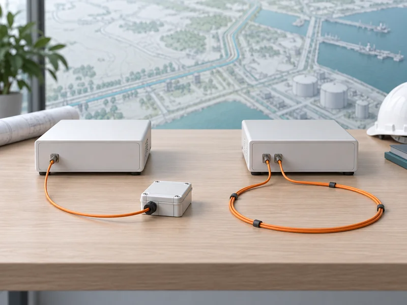
In single-ended measurement, the instrument interrogates the fiber from one end. In double-ended measurement, it obtains information by interrogating from both ends of the relevant sensing path. That bidirectional information can help address differential attenuation along a Raman DTS route, subject to the supported processing method.
Single-ended does not always mean that only one physical fiber runs through the cable. A duplexed arrangement may send the optical path outward on one fiber and return it on another connected at the remote end. Whether that path is interrogated from one end or both remains a separate question.
| Term | What It Describes | What It Does Not Prove |
| Single-Ended | Interrogation from one end of the measurement path | That every cable contains only one fiber |
| Double-Ended | Measurements obtained from both ends | Automatic continuity after every cable break |
| Duplexed Route | Co-located outward and return fiber paths | That the interrogator uses a double-ended algorithm |
| Physically Diverse Return | A return path following a different physical route | That both paths have identical thermal exposure |
These distinctions prevent a common procurement misunderstanding: asking for a ring and receiving a design whose actual measurement or failure behavior differs from the intended requirement. Describe the functions that matter instead of relying on one label. The route drawing should make every splice, termination and instrument connection visible.
Why Does Differential Attenuation Matter?
Raman DTS infers temperature from backscattered optical signals whose relative attenuation can affect the result. If losses vary along the route, a simple uniform-loss assumption may be inadequate. Double-ended information can help estimate or compensate those effects where the instrument implements the necessary method.
Research on double-ended Raman DTS calibration demonstrates why bidirectional information can be useful for nonuniform losses. It also shows that calibration and uncertainty remain part of the measurement problem. Double-ended architecture should therefore be evaluated as a method with conditions, rather than described as inherently accurate under every circumstance.
The existing explanation of the fiber optic temperature sensing principle introduces the optical measurement background. For architecture selection, ask how the proposed instrument treats differential loss and what evidence supports the intended route length and connection arrangement. Avoid importing another system’s published accuracy into the specification.
When Is a Single-Ended Route a Practical Choice?
It is practical when only one route end is accessible and the supported calibration approach meets the measurement objective. It can simplify physical connections and remove the need to bring a second endpoint to an available instrument channel. That simplicity is valuable only if performance remains acceptable over the installed path.
Review the expected cable construction, connections, environmental changes and opportunities for later repair. A route with well-understood optical behavior may be easier to verify than one containing undocumented fiber transitions. The decision should be supported by the supplier’s loss assumptions and an appropriate verification plan.
What Must Be Verified at the Remote End?
Verify that the measurement remains useful at the farthest relevant sensing section under the selected acquisition settings. Near-end results alone may not describe the full route. Include a representative thermal verification location where access and the application permit it.
Also check how the system identifies the end of the valid measurement region. A missing route section should be reported as unavailable, not displayed as an apparently normal temperature. Fault reporting is part of usable monitoring even when the measurement architecture is otherwise simple.
When Does Double-Ended DTS Justify the Extra Routing?
It deserves consideration when the supported bidirectional method improves confidence in the temperature result enough to justify additional fibers, access and configuration. The value depends on the loss behavior and required uncertainty. There is no universal route length at which every project should switch architecture.
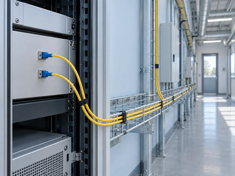
A remote turnaround connection may allow both optical endpoints to reach the instrument through the same physical cable. Another design may provide access to both physical route ends separately. These arrangements differ in maintenance access and exposure to common damage, even if both enable bidirectional measurement.
Does Double-Ended Measurement Always Improve Precision?
No universal claim should be made without identifying the instrument and processing settings. Bidirectional information can improve compensation while acquisition time and noise still influence the reported result. Compare the complete performance specification for each supported mode at the required distance and spatial resolution.
Request a side-by-side test or supplier explanation using the actual proposed settings. A favorable compensation feature does not remove every other source of uncertainty. Reference quality, thermal contact and calibration assumptions still need attention.
What Happens If the Fiber Is Broken?
The surviving coverage depends on where the break occurs, how the fibers are routed and what the interrogator can do after the fault. Some systems may retain measurements from accessible portions while losing the original bidirectional compensation. Others may require a different operating mode or intervention.
Ask the supplier to describe the fault state explicitly rather than treating a loop as a promise of uninterrupted measurement. If two fibers share one cable, one physical incident may affect both. A physically separate return route can change that exposure, but it also changes the installation scope.
- Which sections remain measurable after each defined fault?
- Does the temperature uncertainty or update interval change?
- Is a mode change automatic, supported manually or unavailable?
- How does the operator distinguish degraded data from normal data?
- What verification is required after the repair?
Use the broader guide to DTS troubleshooting when planning restoration. For architecture acceptance, define the expected behavior before deliberately testing an approved fault simulation. The result should document coverage and data quality as well as the presence of a fault alarm.
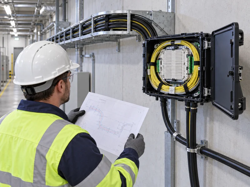
How Should a Project Compare the Options?
Compare them against the same sensing objective, physical coverage and measurement configuration. Separate installation cost from ongoing access and verification effort. A design that looks simpler on an equipment list may be less practical if every reference check requires difficult remote access.
As an illustrative example, a utility gallery with accessible ends may allow several route arrangements, while a one-way installation in a constrained corridor may favor a different approach. The correct decision follows from access, loss behavior and the required fault response. Neither example establishes that one architecture is always preferable for a whole industry.
- Draw the protected route and distinguish sensing fiber from lead fiber.
- Mark accessible endpoints, turnaround splices and reference sections.
- Obtain supplier confirmation of supported measurement modes.
- Compare performance using identical project conditions.
- Define credible faults and the required surviving information.
- Record calibration, repair and verification responsibilities.
What Should Be Included in the Final Handover?
Include the as-built optical diagram, configured measurement mode and evidence supporting the accepted performance. Record what changes when a fault occurs and how the route is returned to normal. Operators should not need to infer coverage from a schematic that lacks the actual software behavior.
For a utility tunnel monitoring project, connect that documentation to the installed route labels and operational procedures. Keep architecture-specific checks within the broader temperature-system reliability program. A clearly documented single-ended or double-ended system is easier to maintain than an ambiguously specified loop.