DTS integration should transmit temperature values with enough context to show where they came from, when they were acquired and whether they remain valid. A receiving platform must distinguish a current normal reading from an old value, a sensor fault or an unavailable route. Connecting an interface is only the beginning of that work.
When specifying distributed temperature sensing fiber optic equipment, request the actual data and alarm interface supported by the proposed configuration. Gato’s E3 product page describes integration through API and Modbus TCP/IP, but the project still needs an agreed point map and behavior definition. Verify the receiver’s treatment of each DTS field through the agreed interface test instead of relying on the protocol name.
What Must Accompany Each Temperature Value?
At minimum, the receiving application needs an unambiguous source, location, unit and acquisition context. It also needs a way to recognize invalid or unavailable information. Without these fields or equivalent interface behavior, a plausible number can be mistaken for a trustworthy measurement.
| Information | Purpose | Typical Integration Mistake |
| Instrument and Channel | Identify the source route | Combining readings from similarly named channels |
| Position or Zone | Connect data to a physical asset | Treating optical distance as a surveyed location |
| Unit and Scaling | Interpret the numeric value | Applying a scale factor twice |
| Timestamp or Age | Show when the data was acquired | Replacing measurement time with display refresh time |
| Quality or Availability | Distinguish usable data from faults | Displaying an unavailable reading as normal |
The interface may package these concepts differently, and some information may need to be maintained by the integration layer. Record the agreed interpretation in a controlled document. Do not invent registers or assume a third-party driver’s default mapping matches the instrument.

How Should Units and Numeric Scaling Be Checked?
Check the documented representation and compare several known values at both ends of the interface. Confirm temperature units, signedness, scale factors and any reserved invalid values. For register-based integration, also verify the documented data type and byte or word ordering where applicable.
A value that looks reasonable during one test can conceal a mapping error. Include negative or boundary values only through a supported simulator or approved test method where the real installation cannot safely produce them. The aim is to test interpretation without creating an unsafe physical condition.
Should the Platform Convert Temperatures?
It may convert them when required for the operator, provided the original unit and conversion are unambiguous. Keep storage, display and alarm evaluation consistent. A Celsius source feeding a Fahrenheit display needs a clear account of which unit the configured thresholds use.
Review exports as well as the live screen. An incident analyst may receive a file with numbers but no unit labels, even though the control-room display looked correct. The exported record should preserve enough context to stand on its own.
How Can Stale Data Be Distinguished from Normal Data?
Use a freshness rule based on the expected acquisition and delivery behavior. When data exceeds its permitted age, the receiving system should identify it as stale rather than quietly preserving its previous normal appearance. The threshold should reflect the actual channel cycle and project requirements.
A successful network poll is not always proof of a new physical measurement. An interface may respond while returning the last available profile. Where acquisition timestamps or sequence indicators exist, use them to distinguish a new profile from a repeated response.
If the source provides no direct measurement-age information, document that limitation and agree on an alternative health indication with the supplier. Do not present a receiver-generated timestamp as if it proves acquisition freshness. The uncertainty should remain visible in both design and acceptance records.
Which Fault States Need Separate Meanings?
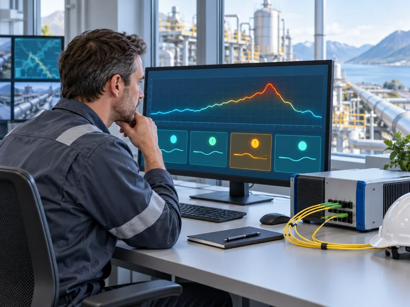
Communication loss, instrument trouble and an unavailable sensing section should not automatically collapse into one generic temperature alarm. Each state implies a different response. A temperature excursion calls for assessment of the asset, while unavailable data calls for attention to the monitoring capability.
The receiving platform should preserve the distinctions supported by the source and clearly identify any that it cannot represent. Avoid replacing missing values with zero, because zero can be a valid temperature. Also check how a recovered connection updates the display and clears or acknowledges the related fault.
- Loss of communication between source and receiver.
- Source instrument or channel fault.
- Invalid or unavailable positions on a sensing route.
- Stale data despite an apparently healthy connection.
- Temperature alarm activation and return to normal.
Use the guide to common DTS problems and solutions to develop the diagnostic responsibilities behind these states. The interface should support that operational distinction. A single red icon without a meaningful reason can slow the investigation.

Should Alarm Logic Live in the DTS or the Receiving Platform?
Choose the responsibility deliberately and document it. The DTS may generate events from its own configured rules, while the receiving platform may display those events or apply additional analysis. Two independent rule sets can create confusing differences unless their purposes are clear.
If the platform recreates an alarm from temperature samples, its sampling interval, persistence and missing-data behavior may differ from the source. An identical threshold does not guarantee identical alarm timing. Verify the intended relationship using recorded profiles and event histories.
What Happens When an Alarm Is Acknowledged?
Acknowledgment should have a defined scope: it may mean that an operator has seen the event, not that the underlying condition has cleared. Confirm whether acknowledgment is local to the receiving platform or synchronized with the source. Test the supported behavior rather than assuming a bidirectional command exists.
Likewise, distinguish event closure, return to normal and alarm reset. These terms can represent different transitions. The existing article on temperature alarm tuning is useful context when defining the source rules that the integration must preserve.
How Should Route Positions Be Mapped to Assets?
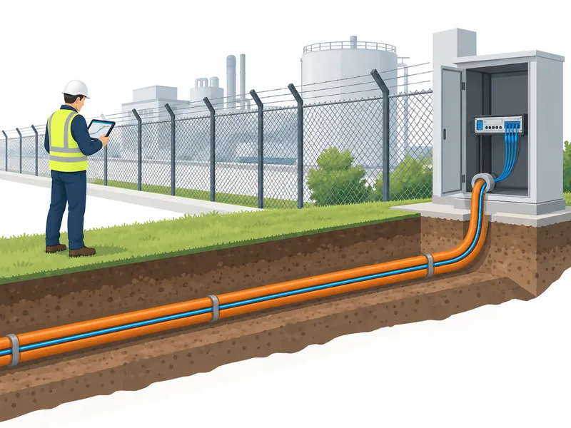
Maintain a controlled relationship between channel distance and the physical route or asset. Lead fiber, service loops and repairs can change that relationship. A position value becomes operationally useful only when responders can translate it into a location they can find.
Zone identifiers should remain stable enough to support histories and exports, while visible labels can reflect the site’s naming convention. Record how changes are approved and propagated. Updating a drawing without updating the receiving system can leave the screen pointing to the wrong place.
As an illustrative example, a gallery might associate several optical intervals with separate access sections. A repair that adds fiber before those intervals could shift the mapping even though the monitored assets have not moved. The integration handover should identify who revalidates that association.
What Tests Demonstrate That the Integration Works?
Test normal data, abnormal conditions and recovery using an approved plan. Compare the source’s own view with the receiving application and retain timestamps. The acceptance record should show not just that messages arrived, but that their meaning remained correct.
- Verify source identity, channel, position, unit and scaling.
- Confirm that new profiles can be distinguished from repeated data.
- Demonstrate the agreed stale-data behavior.
- Check supported source faults and communication interruption.
- Verify alarm activation, acknowledgment and return-to-normal semantics.
- Restore normal operation and confirm that histories remain understandable.
- Export a sample incident and review it independently.
Where SAM300 alarm management forms part of the solution, confirm the exact configuration and supported interactions for the project. Public product descriptions identify capabilities, while the integration document establishes what has actually been implemented. Keep screenshots, point maps and configuration versions together.
Finally, include interface checks within ongoing temperature-system reliability testing. Software changes can alter interpretation even when the fiber and interrogator remain untouched. Reliable integration means that a current value, an old value and a missing value remain visibly different throughout the system’s service life.