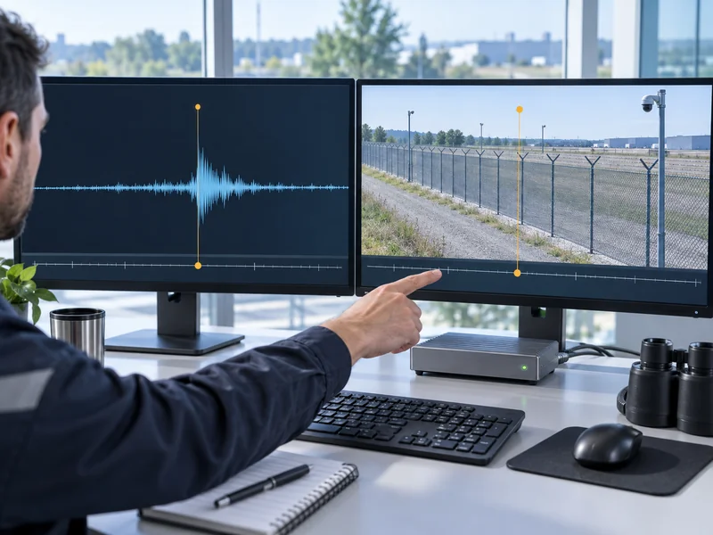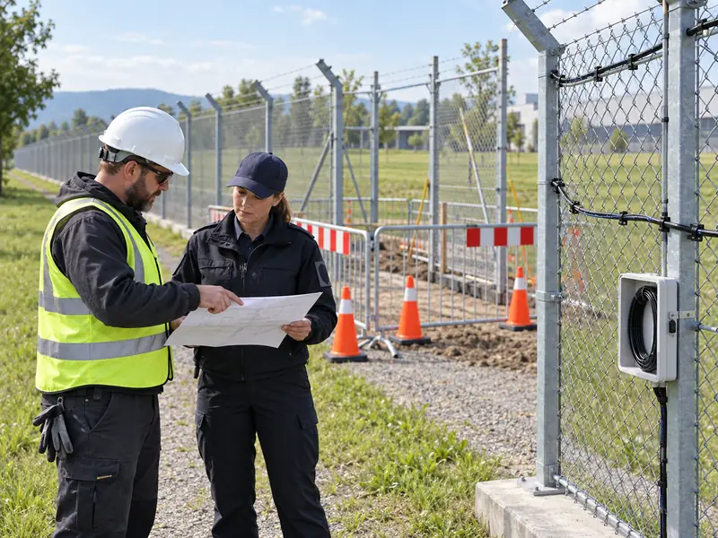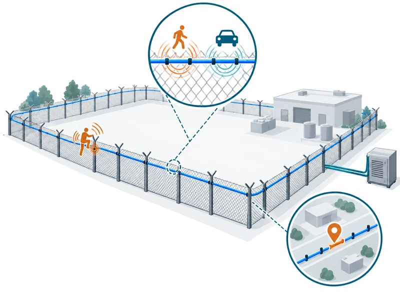

After a DAS fiber repair, restore optical continuity, recheck the relationship between fiber distance and physical location, and repeat detection tests around the repaired section and affected downstream landmarks. A successful splice does not by itself prove that alarm positions remain correct. The repair can change cable length, optical loss, attachment and the route’s local sensing behavior.
For a distributed acoustic sensing system, restoration should therefore include a measurement and mapping handover. The maintenance team and security operator need a shared definition of when coverage is ready to return to service. Keep the repair scope and the verification scope connected.
Which Parts of DAS Behavior Can a Repair Change?
A repair can affect both the optical path and the physical path through which vibration reaches the fiber. Adding a cable section may change the distance assigned to later points. Relocating the cable or changing its attachment can also alter the response near the work area.
A splice enclosure may contain additional slack that occupies optical distance without extending the protected perimeter. That interval should not be interpreted as an equivalent length of fence. Record the relationship between the optical path and the physical route before finalizing the map.
| Repair Change | Possible Effect | Verification Focus |
| Added or Removed Fiber | Location offsets beyond the work | Known landmarks before and after the splice |
| New Splice or Connector | Changed optical loss or reflection | Approved optical measurements |
| New Slack Storage | Optical distance unrelated to perimeter length | Route mapping and sensing treatment |
| Different Attachment | Changed local event transfer | Repeatable physical test events |
| Revised Configuration | Changed zoning or event interpretation | Versioned configuration and targeted regression tests |
What Should Be Preserved Before Repair Work Starts?
Preserve the latest usable configuration, route map and relevant diagnostic records. Identify the last known good state and the actual fault symptoms. These records provide the baseline for deciding what changed during restoration.
Keep a clear account of the affected coverage and the temporary operating arrangement agreed by the site. A repair permit should not be interpreted as permission to leave unrelated zones unavailable. The responsible security team should know the work area and the expected return-to-service process.
- Instrument and channel identifiers.
- Current zone boundaries and location mapping.
- Available optical baseline measurements.
- Relevant event records and fault timestamps.
- Photographs of cable routing, attachment and slack storage.
- The configuration version and responsible approver.
The guide to DAS route qualification explains why cable suitability involves more than continuity. The same principle applies after repair. Preserve enough information to reassess the changed section without unnecessarily repeating unrelated work.
How Should Optical Restoration Be Verified?
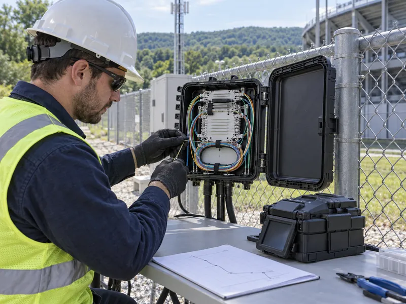
Use the system supplier’s approved optical checks and compare the result with the applicable limits and baseline. Record the new splice position, inserted length and measured changes. A statement that the fiber now passes light is too limited for a complete restoration record.
The instrument may provide route diagnostics, while separate optical test equipment may be required for other checks. Identify which evidence came from which device and retain its settings. Do not confuse an optical fault-location estimate with a verified physical alarm position.
Must Every Repair Use the Same Cable?
Use an approved replacement compatible with both optical and sensing requirements. Matching fiber type alone does not prove that a different cable construction will transfer vibration in the same way. Obtain supplier guidance before introducing a substitute into a monitored section.
Record the replacement cable’s identification and any changes in armor, sheath or installation method. If the physical response differs, the verification plan should address that difference. Avoid hiding a substitution behind the generic description of a fiber splice.
How Can Alarm Locations Be Revalidated?
Use known physical landmarks and authorized test events to compare displayed positions with the as-built route. Include points before the repair, near it and beyond it where added length could affect the mapping. The distribution of checks should follow the route change rather than an arbitrary equal spacing.
A uniform downstream offset may suggest a length-mapping issue, while a local discrepancy may point to slack or a more complex route change. These are investigative clues, not automatic diagnoses. Confirm the actual route and software mapping before applying a correction.
Why Test Beyond the Repaired Section?
Because an upstream length change can alter reported positions for physically unchanged downstream assets. Testing only beside the splice can miss that effect. Include landmarks that demonstrate how the revised map behaves over the affected part of the route.
The distinction between optical distance and physical location also matters when interpreting DAS location-accuracy specifications. A capable instrument cannot compensate for an incorrect site map by specification alone. The mapping evidence must come from the actual installation.

What Local Detection Tests Are Needed?
Repeat representative events in the changed sensing section using the accepted site procedure. Compare the response with the required detection behavior and relevant baseline evidence. Keep event method and configuration controlled so a difference can be investigated meaningfully.
Check transitions between old and new mounting arrangements, enclosure approaches and any rerouted segment. These are places where physical transfer can differ from the original installation. Include unsuccessful trials and the corrective work they triggered.
- Confirm that the intended zone is active under the authorized test arrangement.
- Perform the agreed event at a documented physical point.
- Check detection, classification where relevant and displayed location.
- Confirm the correct event reaches the receiving platform.
- Review linked camera or map behavior if affected by remapping.
- Repeat after any corrective change and retain both versions.
Use SAM300 alarm management or the project’s receiving platform to verify the operator’s actual view. A correct source event is insufficient if the linked zone label or camera mapping still reflects the old route. The handover should include the whole affected chain.
When Is Recalibration or Retuning Appropriate?
Only after the physical and mapping changes have been understood and the supplier’s supported procedure has been identified. Do not retune the whole perimeter simply because one repaired section behaves differently. A local installation issue may need a local physical correction.
If configuration changes are necessary, document their purpose and the sections they affect. Repeat relevant tests to ensure the change has not created a new problem elsewhere. Preserve the previous version so that the comparison remains traceable.
What If the Repaired Section Cannot Meet the Original Requirement?
Keep the limitation explicit and refer the return-to-service decision to the responsible site owner. A reduced capability should not be silently recorded as a completed normal repair. The operator needs an accurate account of what is available while further corrective work is arranged.
An illustrative case is a rerouted segment placed in a mechanically isolating conduit where the original design relied on direct attachment. Optical continuity may be restored while the sensing objective remains unmet. The appropriate decision would depend on testing and an approved revised design, not on the splice quality alone.
What Belongs in the Repair Closeout Package?
Include the physical repair record, updated optical route, revised mapping and test evidence. Identify configuration changes and the person who accepted the restored coverage. The package should make the next maintenance intervention easier to understand.
Use the site’s acceptance-testing framework to define the targeted return-to-service checks. Full recommissioning may be unnecessary when the effect is demonstrably limited, but the affected functions still need proof. A repair is complete when the intended sensing and response behavior has been restored and documented.