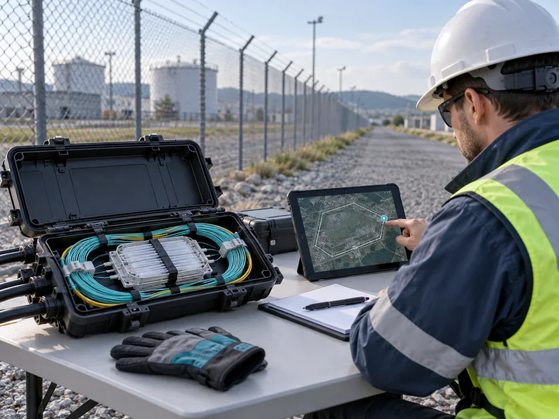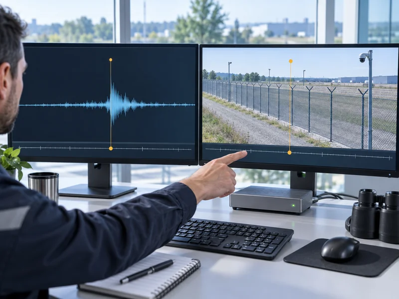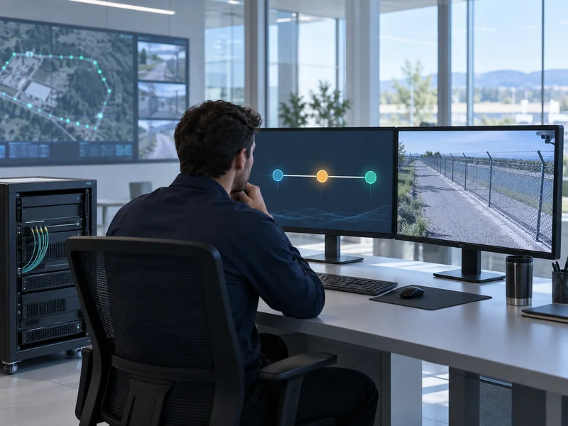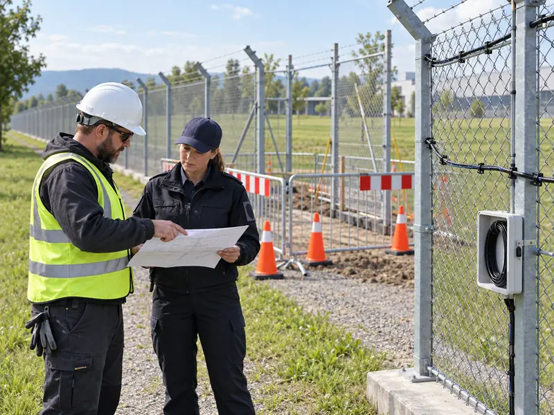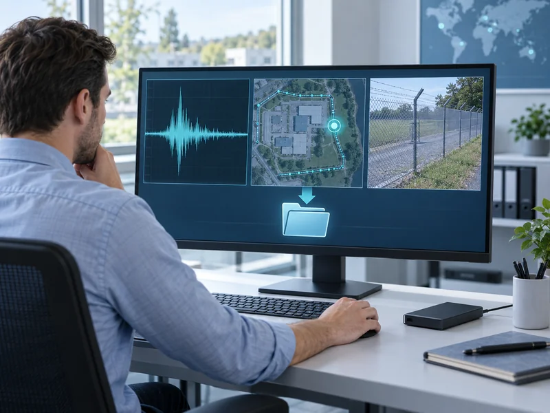
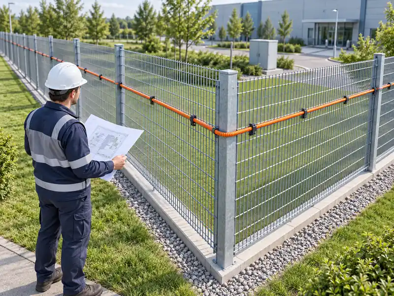
The same disturbance can produce different distributed acoustic sensing signals when the fiber changes direction because conventional straight-fiber DAS responds primarily to strain along the fiber’s axis. Cable construction, coupling and the wave field also influence the measurement. Investigate the local fiber geometry and strain transfer before attributing a smaller DAS signal to degraded interrogator performance.
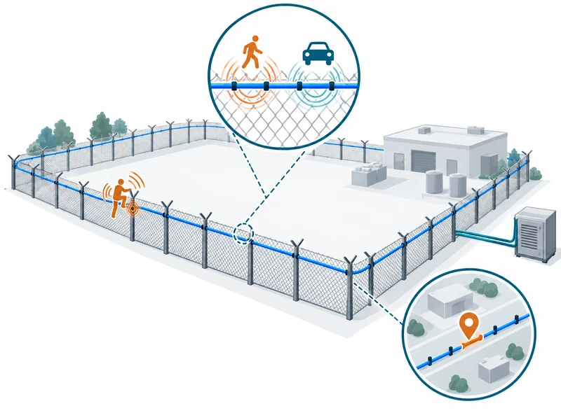
When planning distributed acoustic sensing fiber optics for perimeter protection, evaluate the installed route rather than treating the cable as an equally sensitive microphone in every direction. The practical question is whether representative events remain detectable along the actual boundary. Route geometry is part of that evaluation.
How Does Fiber Direction Influence the Measured Strain?
For conventional DAS, the measurement is related to deformation along the sensing fiber over the instrument’s effective measurement length. A disturbance can produce different axial strain as its propagation direction and motion vary relative to that fiber. The result depends on the local wave field, not simply the distance from the source.
Silixa’s description of its phase-based DAS technology identifies dynamic strain as the measured quantity. That provides useful context for understanding why the physical orientation matters, without implying identical behavior for every interrogator or engineered cable. Specialized fiber arrangements can change directional response and should be assessed using their own supporting data.
Does a Right-Angle Turn Create a Blind Spot?
Not necessarily: a turn changes the sensing direction, but the resulting detection behavior depends on the event and installation. A corner may also involve different supports, attachment or cable slack. A route drawing alone cannot establish either complete coverage or a blind spot.
Test representative events on both sides of the transition and around the corner itself. Record the physical arrangement and settings. This produces evidence about the actual route instead of relying on a simplified geometric assumption.
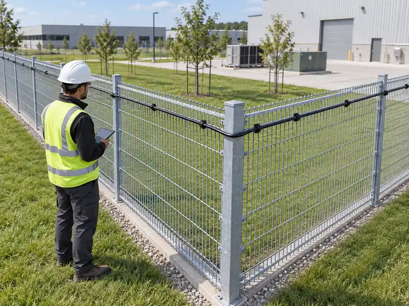
Which Other Factors Can Look Like an Orientation Effect?
Differences in mechanical coupling, source distance, support stiffness and background activity can all change a DAS response. A comparison between two differently oriented sections may also change these factors unintentionally. Keep them in the investigation rather than assigning every difference to direction.
| Changed Condition | Possible Influence | Comparison Method |
| Fiber Direction | Different axial strain response | Document source and route geometry |
| Cable Attachment | Different transfer into the fiber | Inspect and record approved mounting |
| Support Material | Different structural vibration | Group comparable fence or ground sections |
| Source Distance | Different disturbance reaching the route | Use known event positions |
| Processing Settings | Different filtering or classification | Preserve configuration versions |
The existing article on DAS deployment conditions addresses broader site suitability. An orientation review should build on that information. It should not replace the optical and mechanical checks required for a sound installation.
How Can an Orientation Comparison Be Made Fairly?
Use repeatable, authorized events at documented locations and keep the active configuration constant. Choose sections whose physical arrangements are understood. Where the comparison necessarily changes more than direction, record those differences and limit the conclusion accordingly.
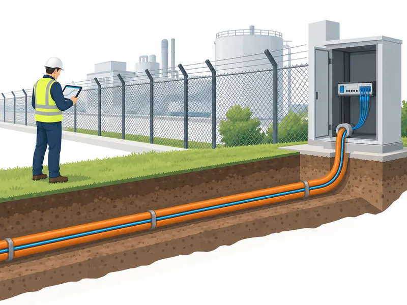
For a fence, inspect whether a corner post or bracing changes the support behavior. For a buried route, note changes in containment or known ground conditions. These details can explain differences that a simple plan view misses.
What Should the Test Record Show?
- The fiber route and the physical direction of each tested segment.
- The event location and its relationship to the route.
- The attachment or burial arrangement known for that section.
- The approved event method and repeated outcomes.
- The relevant signal or event record supported by the instrument.
- The displayed alarm location and configuration version.
Do not select only a favorable trial to demonstrate coverage. Repeatability matters because source execution and environmental activity can vary. The final record should show the range of observed outcomes and any unexplained differences.
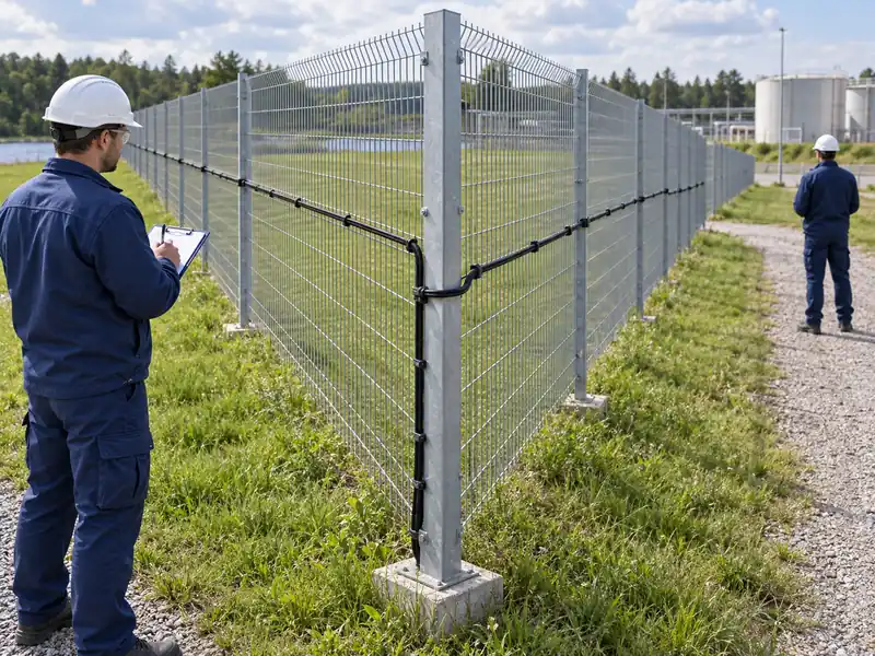
Should the Fiber Be Routed in Extra Loops?
Additional routing may change directional exposure, but it also introduces optical length, installation complexity and mapping requirements. Whether it improves the intended detection depends on cable construction and coupling. Use a supplier-supported design rather than assuming that any loop creates omnidirectional sensing.
A service loop stored loosely in an enclosure is particularly different from a deliberately engineered sensing arrangement. Its extra length may have little useful relationship to the protected boundary. The software map should distinguish stored slack from physically extended perimeter coverage.
Review the F7 installation guidance and obtain project-specific advice for unusual geometry. Cable bend limits and attachment requirements remain applicable. A routing change should be verified physically and reflected in the distance map.
Can Software Completely Correct Directional Sensitivity?
Software can process the signal that the installation delivers, but it cannot assume that every event produces the same physical strain at the fiber. Classification and filtering may help distinguish events under supported conditions. They do not justify ignoring a weak or inconsistent physical response.
A local configuration adjustment may be appropriate after the route has been evaluated. Document what it is intended to change and check the nuisance-alarm consequences. Applying a broad sensitivity increase without understanding the geometry can alter unrelated parts of the perimeter.
What Evidence Should Accompany a Claimed Improvement?
Require a before-and-after comparison using the same event method and documented physical conditions. Preserve the settings and outcomes for unsuccessful trials as well. The evidence should show improved performance for the relevant event, not merely a larger signal amplitude.
The article on improving DAS alarm accuracy provides the broader tuning context. Orientation testing narrows one physical source of variability. Keep that distinction clear when deciding whether a configuration change has solved the actual problem.
How Should Corners and Route Transitions Be Handed Over?
Identify them explicitly in the as-built route and include their verification evidence. A long straight section should not be the only basis for accepting a boundary with several different geometries. Maintenance teams also need to know which changes would invalidate the tested arrangement.
As an illustrative example, a site might route the cable along a fence before turning onto a rigid wall. That transition changes direction and supporting structure together. The handover should describe both changes and the tests demonstrating the required behavior on each side.
- Mark geometry and installation transitions on the route drawing.
- Associate each test record with a physical landmark.
- Record approved local settings and their scope.
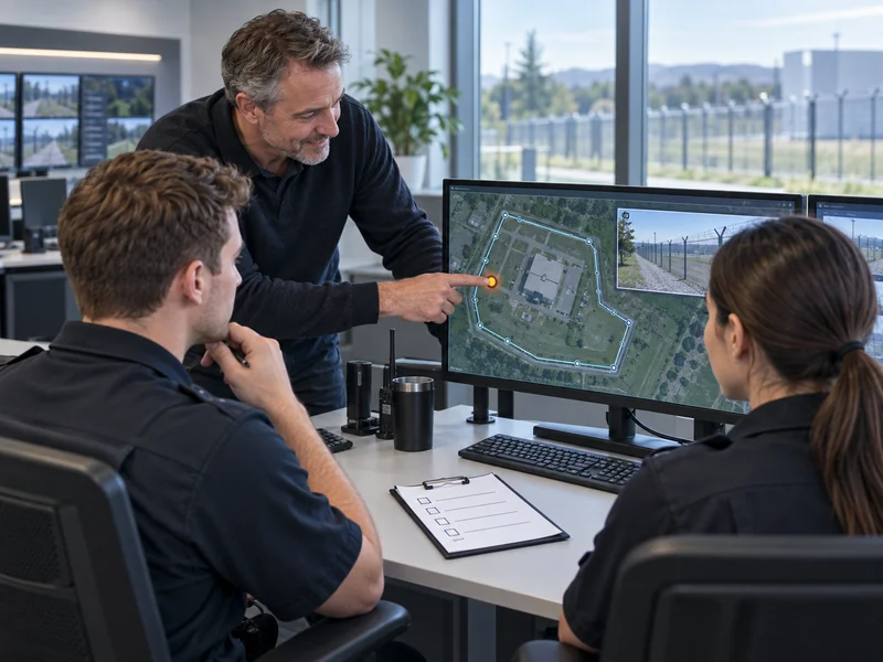
- Verify that alarm locations remain understandable to operators.
- Require targeted retesting after relevant repairs or rerouting.
What Should Operators Understand About Different Signal Strengths?
They should understand that amplitude differences do not directly measure threat severity. Geometry and coupling can change the observed signal even when the event is similar. The operational response should follow the configured event information and verification procedure.
Where SAM300 provides the alarm and map interface, ensure the physical route labels remain accurate after any routing adjustment. Clear locations help operators verify an event without interpreting raw strain physics in real time. Engineering records should explain the directional assessment behind the accepted installation.
A useful DAS route is one whose response has been demonstrated for the site’s relevant conditions. Directional sensitivity is a reason to design and test carefully, not a universal reason to reject or endorse a cable layout. Documented comparisons turn the geometry into an engineering decision that can be revisited after change.