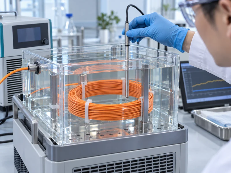
DTS calibration reference sections should expose a known length of sensing fiber to a stable, independently measured temperature while preserving the cable’s installation limits. Their position, usable length and treatment in the instrument software must match the calibration method. A reference section becomes useful evidence only when its temperature, location and measurement conditions are recorded together.
For a distributed temperature sensing fiber optic system, this is a measurement-quality question rather than a reason to change factory settings casually. Some systems use internal references, others allow external reference sections, and the supported procedure varies. Confirm the approved method before specifying equipment or planning a field adjustment.
What Is a Reference Section Supposed to Prove?
A reference section establishes a relationship between the DTS output and an independently known thermal condition at a defined part of the fiber. Depending on the method, its data can support calibration, compensate an instrument effect or verify an already calibrated system. Those uses should be distinguished in the project documentation.
Calibration changes or determines measurement parameters; verification checks whether the output meets a stated requirement. A technician comparing two temperatures has not necessarily performed a valid calibration. Record which activity was undertaken and which settings, if any, changed.
Why Keep a Separate Verification Section?
A separate verification section helps determine whether the calibration behaves sensibly outside the data used to establish it. Reusing the same reference data as the only proof of accuracy can make an apparently good result less persuasive. Where the approved procedure permits it, reserve an independent condition or location for validation.
Published research on Raman DTS calibration distinguishes reference measurements from independent validation and discusses the influence of differential attenuation. These are useful engineering principles, but a research algorithm should not be applied to an industrial instrument without checking compatibility. Ask the supplier how the delivered system implements and records its own calibration process.
Where Should Reference Sections Be Located?
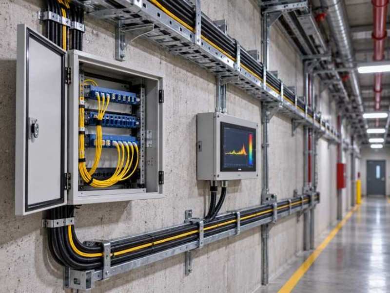
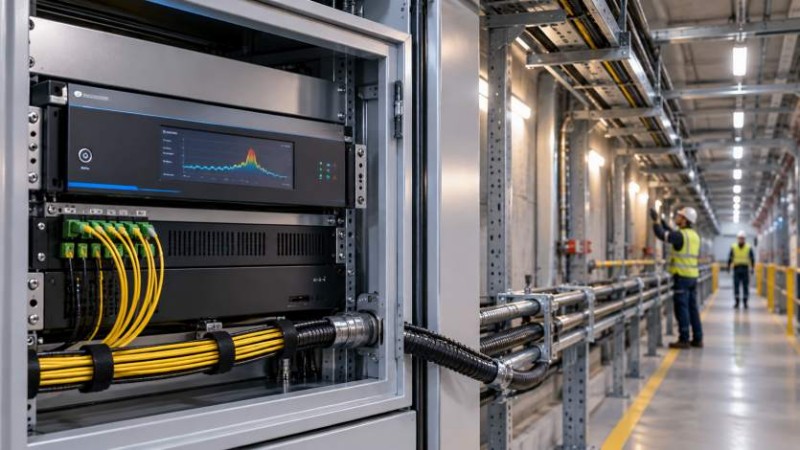
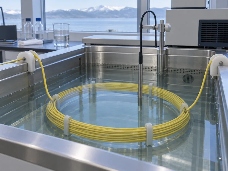
Place them where the thermal condition can be controlled or measured reliably and where their optical positions are unambiguous. The appropriate positions depend on the sensing architecture, loss distribution and calibration procedure. A convenient cabinet location is not automatically representative of a remote route.
A reference near the interrogator may be accessible for routine checks, while a more distant section may provide evidence about performance after additional cable and connections. Select the locations required by the supported DTS procedure rather than automatically installing a near-end and far-end pair. The approved measurement model determines what information the reference arrangement needs to provide.
| Planning Question | Reason It Matters | Record to Keep |
| Can the condition be kept uniform? | Temperature gradients can invalidate a simple comparison | Reference arrangement and stability observations |
| Is the optical position known? | Lead fiber and slack can shift the selected samples | Start and end distances in the instrument |
| Can staff inspect the section? | Routine access supports repeatable verification | Access method and responsible role |
| Does the location suit the method? | Different architectures require different calibration information | Supplier-approved procedure and revision |
Also consider local influences such as direct sun, cabinet ventilation and heat from nearby equipment. A reference device and fiber can share a room while experiencing different temperatures. Their thermal relationship must be demonstrated rather than inferred from distance alone.
How Much Fiber Must Be in the Reference Environment?
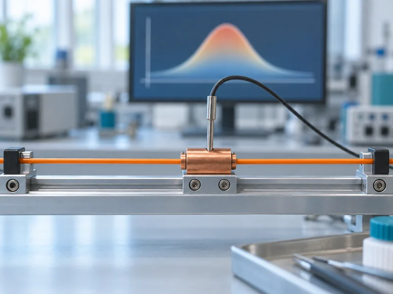
Use enough fiber to obtain a stable measurement region away from thermal transitions, following the instrument’s specified spatial response and calibration procedure. Output points spaced closely together are not necessarily independent measurements. Judge the usable reference length from the DTS spatial response and the thermal boundaries, not the number of points plotted on screen.
At each end of a heated or cooled section, the instrument may report a transition influenced by adjacent temperatures. Selecting only the intended stable interior reduces the risk of treating an edge as the reference temperature. The required exclusion distance must come from the actual system behavior, not a universal rule copied between instruments.
Can the Fiber Be Coiled?
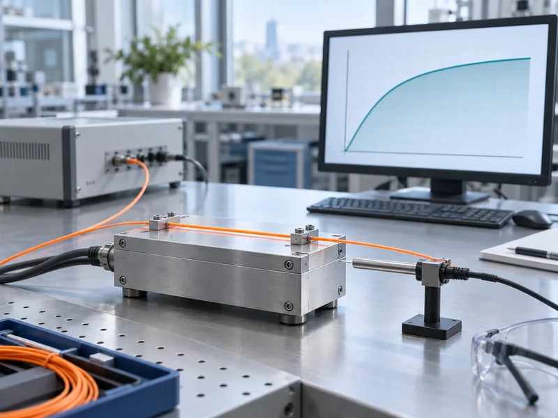
Coiling may make a reference arrangement practical, but the cable must remain within its bend and installation limits. The entire selected length also needs an adequately uniform thermal environment. A tightly packed coil with trapped air or uneven exposure can undermine the purpose of the reference.
Protect entry and exit sections from mechanical strain and identify them in the route record. Avoid selecting an interval that includes cable outside the controlled region. Understanding the DTS measurement principle helps explain why an apparently simple physical arrangement needs careful optical-distance mapping.
What Should Be Checked About the Independent Thermometer?
The reference thermometer should be suitable for the temperature range, environment and uncertainty needed for the verification. Its identification and calibration status should be recorded, together with the probe position and the logging method. A high-resolution display alone does not demonstrate reference accuracy.
Check that the reference probe measures the same condition as the selected fiber interval. Contact quality, immersion depth, local gradients and thermal response can all affect the comparison. If the environment is changing, a timing mismatch between the reference logger and DTS profiles can create an apparent error even when both devices function correctly.
- Identify the thermometer and probe, including the relevant calibration record.
- Record the probe’s position relative to the sensing fiber.
- Confirm a stable interval before calculating a comparison.
- Preserve timestamps and the actual averaging method.
- Include reference uncertainty when judging the result.
Do not claim a smaller uncertainty than the complete arrangement supports. The reference instrument, thermal uniformity, timing and DTS repeatability all contribute to the interpretation. A measurement specialist can establish the appropriate uncertainty treatment for a contractual accuracy requirement.
How Should Splices and Loss Changes Be Handled?
Record their positions and assess them using the supported calibration procedure because optical loss changes can influence Raman DTS interpretation. The effect is particularly relevant when losses differ between the measured Raman components. A simple offset adjustment may not resolve a route-dependent error.
After repair or rerouting, verify that the reference interval still corresponds to the intended physical section. Added cable can shift optical distances and invalidate previously selected windows. Recheck the configuration before interpreting a mismatch as instrument drift.
The guide to common DTS problems and solutions provides broader diagnostic context. For reference work, keep the investigation focused on thermal stability, reference validity, optical mapping and the approved compensation method. During diagnosis, hold the reference arrangement steady while evaluating one suspected influence on the DTS reading.

Which Records Make a DTS Reference Check Reproducible?
It should allow another engineer to repeat the comparison and understand exactly what passed. Keep raw or exported readings where available, not only a photograph of a favorable display. Attach the interrogator identity, route drawing, active settings and observed thermal conditions to the comparison data.
- State the purpose: commissioning calibration, periodic verification or investigation.
- Identify the reference section’s physical location and optical start and end positions.
- Document the thermometer, thermal arrangement and stability criteria.
- Record integration, averaging and channel settings.
- Compare time-aligned readings over the agreed stable interval.
- Report deviations, applicable uncertainty and the acceptance decision.
- Record configuration changes separately and retain the previous version.
In an illustrative cable-gallery project, the handover might include photographs of the reference mounting, a route sketch, paired readings and the supplier-approved procedure. These records would explain why the comparison was meaningful at that time. They would not prove that every point on the installed route has identical performance.
When Should Reference Sections Be Rechecked?
Recheck them at the planned maintenance interval and after changes that could affect the measurement or its mapping. Examples include cable repairs, instrument replacement, a revised calibration procedure or a substantial unexplained shift. The exact interval should reflect the application and supplier guidance.
For sites using centralized alarm management, assign ownership for investigating a failed verification and recording any temporary operating limitations. A reference discrepancy must not silently become an accepted new baseline. Operations staff need to know whether temperature data remains usable while the issue is investigated.
Combine this focused procedure with long-term reliability checks of the wider installation. Well-documented reference sections make changes easier to diagnose and results easier to defend. Their value comes from repeatable conditions and traceable decisions, not from having a calibration label alone.