Distributed temperature sensing fiber optic response time depends on how quickly heat reaches the sensing fiber, how the instrument acquires a temperature profile, and when the alarm logic accepts that profile as an event. A fast screen refresh therefore does not prove that an installed cable will warn quickly about a developing hotspot. Evaluate the complete path from a defined thermal change to the alarm delivered to the operator.
This distinction matters when planning distributed fiber optic temperature monitoring for cable galleries, industrial equipment and other extended assets. The useful question is whether the installed arrangement detects the specified condition within the project’s agreed time, under representative operating conditions. That requires a test definition as well as an equipment specification.
What Does DTS Response Time Actually Include?
It includes several overlapping processes, each with a different owner and a different opportunity for delay. Heat must travel from the source through the surrounding material and cable construction before the fiber experiences a temperature change. The interrogator then estimates temperature, evaluates the configured rules and passes an event through the receiving system.
| Stage | What Can Delay It | What to Record |
| Heat Transfer | Air gaps, insulation, protective layers and distance from the source | Cable placement and independent reference temperature |
| Profile Acquisition | Integration time, channel sequence and processing | Actual profile timestamps and active settings |
| Alarm Decision | Persistence, averaging and configured thresholds | Rule definition and first qualifying profile |
| Alarm Delivery | Polling, queues and communication interruptions | Source event time and operator display time |
These stages should not automatically be added as independent fixed delays because acquisition and heat transfer can occur together. Instead, measure the observable milestones and identify which stage governs the result. A single headline response number conceals that distinction.

Why Can a Protective Cable Respond More Slowly?
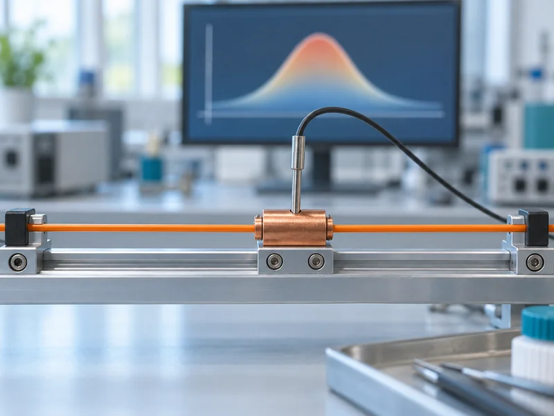
The glass senses its own thermal condition, so protective construction can affect how quickly the surroundings influence the measurement. A sheath, loose tube, mounting channel or intervening air space changes the path through which heat reaches the fiber. Mechanical robustness and rapid thermal response must therefore be considered together.
A sensing cable resting against an asset and the same cable suspended nearby do not necessarily measure the same temperature or respond at the same rate. Contact, airflow and the source geometry all matter. Select an installation that represents the intended measurement rather than assuming that proximity guarantees useful contact.
Should the Cable Always Touch the Monitored Asset?
No: the correct placement depends on whether the project needs an asset surface temperature, local air temperature or another defined thermal quantity. A tunnel installation monitoring ambient heating has a different objective from a cable arrangement intended to follow equipment surface changes. The mounting specification should identify that objective explicitly.
Use manufacturer-approved attachment methods and protect the cable from crushing, unsuitable bend radii and incompatible materials. A faster response obtained by removing required protection is not a valid improvement. Where two cable constructions are being compared, test both in the proposed installation rather than relying on jacket thickness alone.
Is the Profile Update Interval the Same as Detection Time?
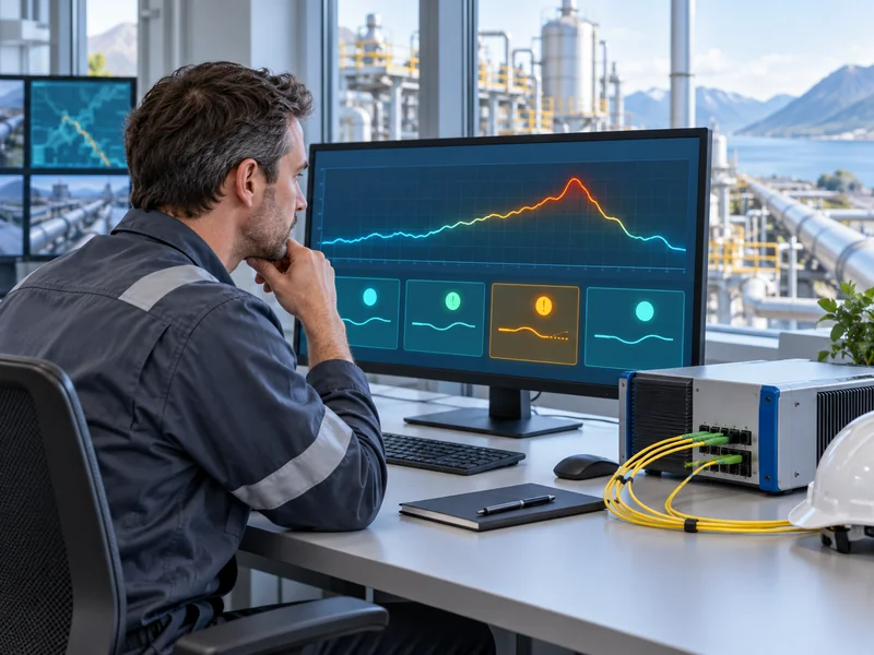
No: an update interval tells you when another profile becomes available, while detection time describes when a defined event is recognized. Temperature estimates may use integration or averaging, and a multi-channel arrangement may acquire different routes in sequence. A frequently refreshed display can also redraw an older value if the data interface is poorly designed.
The US Environmental Protection Agency’s technical explanation of fiber optic DTS describes the tradeoff between integration, spatial resolution and measurement precision. This supports a practical procurement rule: request performance under one stated configuration, rather than combining the best individual figures from unrelated settings. It does not establish a response time for a particular Gato installation.
Which Settings Should a Supplier Identify?
- The acquisition and output interval for each active sensing channel.
- The integration or averaging settings used to produce each profile.
- The spatial resolution and the actual output sample spacing.
- The alarm persistence, reset conditions and any further filtering.
- The receiving platform’s polling interval and stale-data indication.
Request a configuration export or a clear settings record alongside the test result. Without it, a later change can make the original timing result difficult to reproduce. For the optical background behind these settings, see the explanation of the fiber optic temperature sensing principle.
How Does Hotspot Size Affect the First Alarm?
A short heated section can produce a smaller reported peak than a longer section at the same actual temperature because the measurement resolves temperature over a finite length. If the reported peak crosses the alarm threshold later, this can appear to be a timing problem. In reality, the heated length and the system’s spatial response may be the controlling factors.
The test must therefore specify both the thermal exposure and its extent along the cable. Heating a long coil uniformly may verify one aspect of response while failing to represent a compact hotspot on a straight installed route. Neither result should be generalized to the other arrangement without supporting evidence.
As an illustrative planning example, consider a cable gallery where concern centers on localized heating near a joint. A representative evaluation would identify the expected heated region, sensing-cable placement and reference measurement before choosing the test method. The example is a design discussion, not a claim that DTS measures the internal conductor temperature directly.
How Should Alarm Persistence Be Evaluated?
Persistence should be evaluated as part of the agreed detection objective, not treated as an invisible software detail. Requiring a condition to remain present can reduce transient alarms, but it can also delay notification. Changing persistence without reviewing the required warning time trades one behavior for another.
Absolute temperature rules, rate-of-rise rules and local comparison rules may respond differently to the same exposure. Define which rule is expected to operate and how overlapping events are handled. Where a platform supports multiple conditions, test their actual interaction rather than assuming that the earliest condition always wins.
The existing guide to reducing false alarms in temperature monitoring provides the broader tuning context. For response-time work, keep a versioned record of every relevant setting and compare results only when the configuration differences are understood. Avoid lowering a threshold simply to obtain an attractive timing result.
What Makes a Response-Time Test Repeatable?
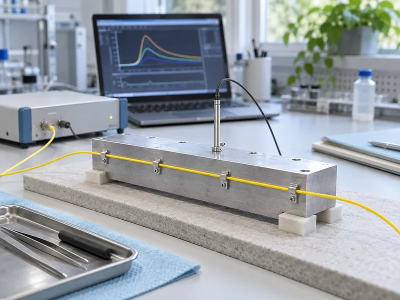
A repeatable test defines the physical arrangement, the initial condition, the thermal stimulus and the timing milestones before the exposure starts. It also uses an independent reference measurement suitable for the same physical quantity being assessed. Comparing a surface reference with a nearby air-sensing cable can otherwise lead to a misleading conclusion.
- Document the cable model, route position, attachment and heated length.
- Record the starting thermal condition and relevant ventilation or ambient changes.
- Capture the active acquisition and alarm configuration.
- Apply an approved, controlled thermal stimulus appropriate to the asset and cable limits.
- Record reference readings, DTS profiles, alarm creation and receiving-platform timestamps.
- Repeat after a defined recovery period and investigate substantial differences.
Do not improvise heating on energized equipment or use a test that risks damaging the asset. The responsible engineering team should approve the method and the limits. For an operational cable gallery, a representative test fixture may be more appropriate than heating equipment in service.
When Should the Clock Start?
Start at a documented milestone that reflects the requirement: for example, a reference sensor reaching the agreed condition rather than someone switching on a heater. Heater activation does not mean the cable immediately receives that heat. Preserve both times if they answer different engineering questions.
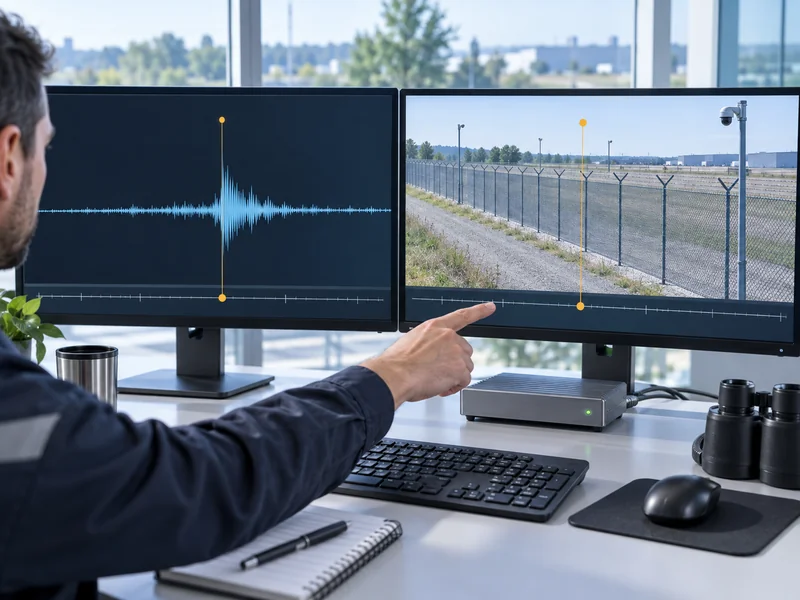
Also identify the end milestone: interrogator event creation, platform receipt or visible notification to the operator. Synchronize the recording devices or measure their clock offsets before comparing timestamps. A result with an undefined start or end cannot reliably demonstrate compliance with a timing objective.
How Should the Findings Influence a DTS Specification?
Specify an installed-system behavior with stated conditions, then require evidence under those conditions. Include the cable construction, route arrangement, heated length, settings and alarm destination in the acceptance record. This creates a testable requirement without pretending that one laboratory figure covers every site.
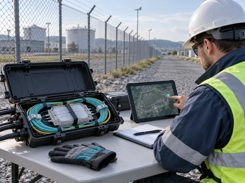
For a utility tunnel temperature monitoring solution, the relevant handover should explain what the system measures, how warnings reach the control room and which configuration changes require another check. Keep timing results together with the as-built route information. Later investigators can then distinguish installation changes from instrument behavior.
Use long-term temperature-system reliability testing to complement this initial evidence as the installation ages. Response-time testing answers how a defined exposure becomes an alarm; continuing verification checks whether that behavior remains dependable. Both are useful when their scope and limitations are recorded honestly.