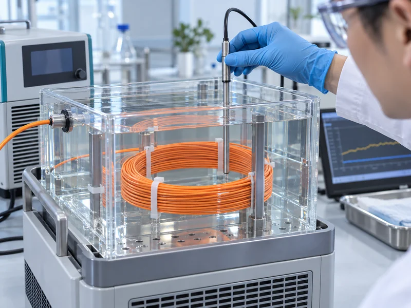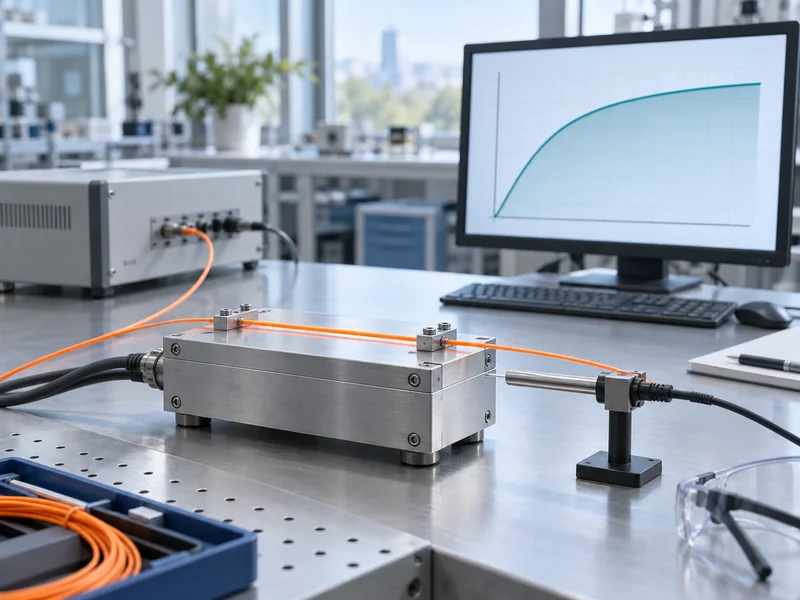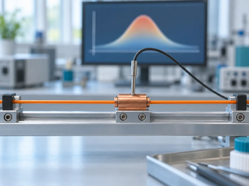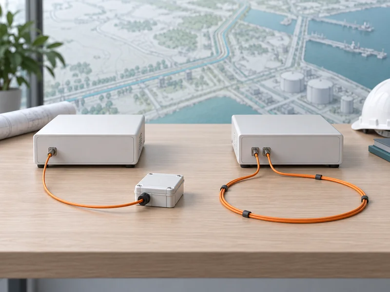
The cost of a Distributed Temperature Sensing (DTS) fiber optic system depends on more than equipment prices. Key factors include sensing distance, fiber selection, installation complexity, software integration, and maintenance. Even projects covering the same distance can have different costs due to site conditions and installation requirements.
Effective DTS budgeting should focus on the total cost of reliable temperature monitoring rather than the cost per kilometer. This article explores major cost factors, hidden expenses, and practical budgeting strategies.
What Is Included in a DTS Fiber Optic System Budget?
A typical distributed temperature sensing fiber optic system consists of a monitoring unit, sensing fiber optic cable, optical connections, monitoring software, and associated installation and commissioning services.
The monitoring unit sends optical signals through the fiber and analyzes returned signals to determine the temperature distribution along the sensing route. In Raman-based DTS systems, temperature-dependent backscattering provides the information used to reconstruct the temperature profile.
However, purchasing these components does not automatically create a functioning monitoring system. The sensing cable must be positioned correctly, the optical link must satisfy performance requirements, and temperature alarms must correspond to actual equipment locations.
Main DTS Project Cost Components
| Cost component | What the budget covers | Main cost driver |
| DTS monitoring unit | Interrogator, channel configuration, measurement capability | Channels, sensing range, required performance |
| Sensing fiber cable | Fiber and protective cable construction | Length, environmental protection, cable type |
| Installation | Cable pulling, mounting, routing, mechanical protection | Accessibility and installation complexity |
| Splicing and termination | Fusion splices, connectors, enclosures | Number of connections and termination points |
| Software and integration | Temperature visualization, alarms, external interfaces | Integration scope and licensing |
| Commissioning | Optical testing, calibration checks, alarm verification | Number of zones and acceptance requirements |
| Maintenance | Inspections, repairs, software support | Site conditions and service arrangements |
A complete quotation should specify which of these items are included. Equipment-only prices are useful for preliminary comparisons but should not be treated as complete project costs.
DTS Monitoring Unit Cost: Why Channel Configuration Matters
The DTS monitoring unit is often one of the most significant individual equipment expenses. Its cost depends on the required sensing distance, available measurement channels, temperature measurement specifications, and software functionality.
Longer sensing distances can place greater demands on signal processing and the optical link. Required measurement time and temperature uncertainty must therefore be considered alongside the advertised maximum range.
More Channels Don’t Necessarily Deliver Better Value
Consider an industrial facility with four separate monitoring areas. A multi-channel DTS unit may allow those areas to connect to one central monitoring platform, reducing the need for independent interrogators.
However, a centralized architecture also introduces practical considerations, including cable routing, fault isolation, maintenance access, and the consequences of a shared monitoring-unit failure.
GATO Security lists 2-, 4-, 8-, and 16-channel configurations for its E3 DTS range, along with single-channel sensing distances of up to 16 km, depending on configuration. These specifications provide useful initial design boundaries, but project suitability still depends on optical loss, installation conditions, and required measurement performance.
An important budgeting question is not simply how many channels are available, but how many independently routed sensing circuits the project actually needs.
Before selecting a monitoring unit, engineers should determine:
- The physical length of each sensing route.
- Whether different monitoring areas require independent channels.
- The expected optical losses from cable, splices, and connectors.
- The required measurement interval and response characteristics.
- Whether future expansion is probable or only theoretical.
Buying unused channels for a future project that may never materialize can increase initial expenditure without delivering immediate operational value.
Fiber Optic Cable Cost: Why the Cheapest Option Isn’t Always the Most Cost-Effective
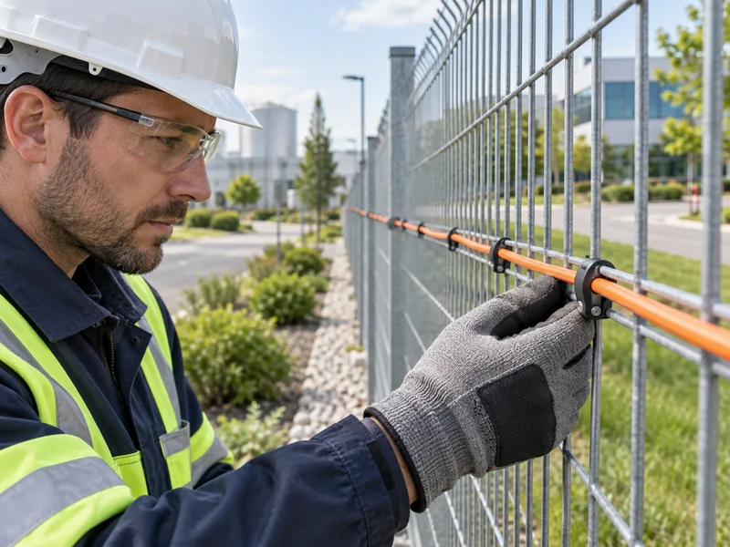
Sensing fiber represents a different budgeting challenge. Although individual fiber strands may be relatively inexpensive, the complete sensing cable must withstand the mechanical and environmental conditions of its installation.
A cable installed inside a protected indoor tray does not face the same requirements as one exposed to moisture, vibration, crushing forces, chemicals, or outdoor temperature variations.
How Installation Conditions Influence Cable Selection
| Application | Important cable considerations | Potential budget impact |
| Power cable tunnel | Fire safety, routing protection, thermal contact | Mounting accessories and installation labor |
| Oil and gas pipeline | Mechanical protection, environmental exposure | Armored construction and protective routing |
| Industrial equipment | Bending resistance, attachment method, vibration | Specialized fastening and routing work |
| Underground infrastructure | Moisture resistance, pulling forces, repair access | Protection and excavation requirements |
| Warehouse monitoring | Support structure, coverage layout, maintenance access | Cable supports and installation labor |
GATO Security describes sensing cable using GI 62.5/125 multimode fiber with protective polymer materials and an armored sheath. This is relevant when preparing a compatible system specification, but cable suitability should be verified against the actual site conditions and DTS unit requirements.
Why Cable Length and Asset Length Are Not Identical
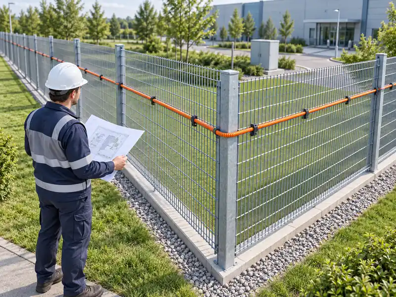
A common budgeting mistake is estimating sensing fiber length directly from the length of the monitored asset.
A 2 km industrial cable route might require additional fiber for entry and exit paths, routing around obstacles, connecting to the monitoring cabinet, and allowing service loops at termination points.
In some projects, both sides of an asset or multiple cable circuits must be monitored. In others, one strategically positioned sensing route may be sufficient.
The correct calculation starts with the physical cable layout rather than the distance shown on a site drawing.
Installation and Construction Can Change the Entire Budget
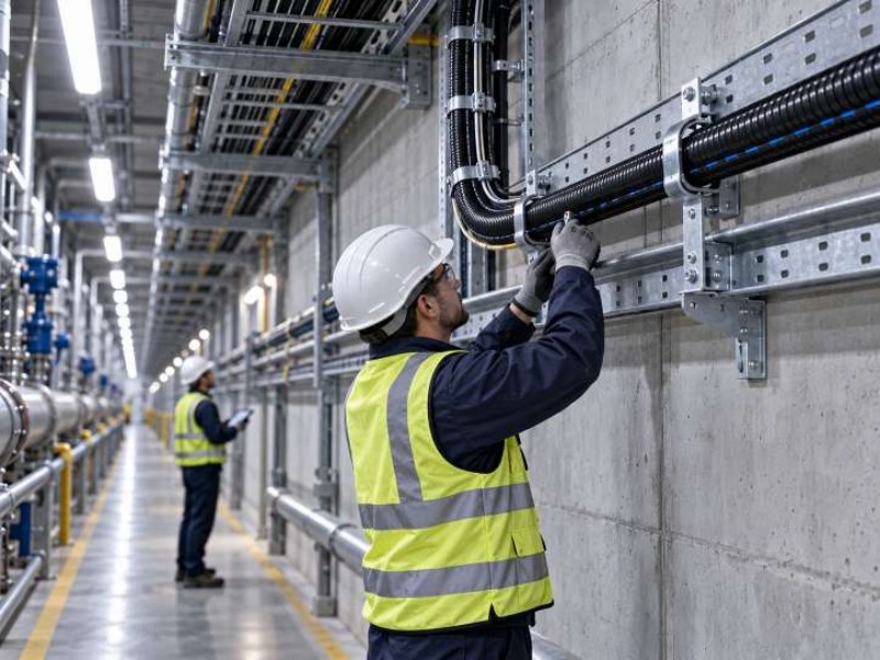
Installation conditions frequently explain why DTS projects with similar equipment specifications have different total costs.
In a newly constructed utility tunnel, engineers may be able to install sensing fiber alongside other cable infrastructure. In an operating facility, installation may involve limited access periods, additional safety supervision, work permits, or temporary shutdown coordination.
The second project can require considerably more labor even when it uses less sensing fiber.
Four Installation Factors Worth Evaluating Early
- Existing infrastructure: Available trays, conduits, and cable supports may reduce construction work, provided capacity and compatibility are confirmed.
- Access restrictions: Confined spaces, elevated locations, and hazardous areas can increase installation time and safety requirements.
- Thermal contact: Poor positioning may cause the fiber temperature to differ from the temperature of the monitored asset.
- Future maintenance: Routes that are difficult to inspect may create additional repair expenses.
The third factor deserves particular attention. DTS measures temperature along the sensing fiber; it does not automatically measure the internal temperature of a nearby power conductor.
A cable placed near equipment without consistent thermal coupling may provide a different temperature response from a properly attached sensing cable.
Reducing installation cost by compromising sensing placement can create a system that is inexpensive to install but unsuitable for its intended monitoring objective.
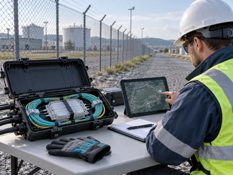
Splicing, Connections, and Optical Loss: Small Items with Large Consequences
Fusion splicing, connectors, and protective enclosures may appear to be secondary expenses, but their quality directly affects the optical performance of the finished installation.
Each optical connection introduces some level of signal loss. Excessive accumulated attenuation can reduce the useful sensing range or compromise measurement quality, especially toward the far end of a long sensing route.
This makes optical budgeting essential before finalizing the equipment configuration.
Example: Comparing Two Fiber Layouts
Consider two hypothetical designs for the same industrial facility.
| Design factor | Layout A | Layout B |
| Sensing coverage | Same target assets | Same target assets |
| Cable routing | Direct route | Multiple detours |
| Splice locations | Fewer | More |
| Installation access | Mostly accessible | Several restricted areas |
| Optical-loss risk | Potentially lower | Potentially higher |
| Maintenance complexity | Simpler | More complicated |
Layout B may require more cable, splice enclosures, installation labor, and documentation. It may also need additional optical verification before commissioning.
A short route is not necessarily the best route if it introduces unacceptable mechanical risks. The objective is to balance installation feasibility, thermal contact, signal quality, and maintainability.
GATO Security’s technical guidance also identifies poor splicing, contaminated connectors, bending, and excessive route length as possible causes of weak optical signals.
Software, Platform Integration, and Alarm Design Costs
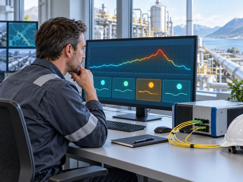
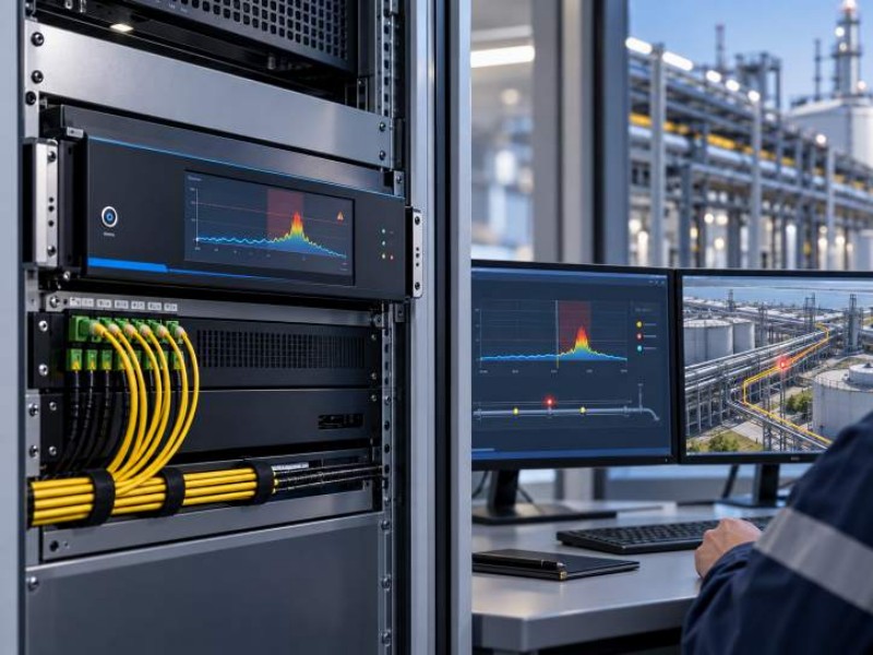
Monitoring software converts temperature measurements into information that maintenance and safety teams can use.
A basic installation may only require temperature profiles, historical records, and alarm notifications. A larger industrial facility may need integration with an existing supervisory control system, security platform, or centralized monitoring environment.
Which Software Functions Actually Affect the Budget?
| Function | Practical purpose | Budget consideration |
| Temperature visualization | Displays temperature along the sensing route | Included functions and licensing |
| Alarm zoning | Defines different alarm conditions by location | Configuration and testing effort |
| Historical data | Supports temperature trend analysis | Storage and retention requirements |
| Asset mapping | Links fiber distance to physical equipment | Survey and mapping labor |
| External integration | Transfers alarm data to another platform | Protocol engineering and acceptance testing |
| Video linkage | Associates temperature alarms with camera views | Camera mapping and integration work |
For example, GATO Security’s E3 solution describes browser-based monitoring, configurable alarm zones, and historical temperature queries. Its SAM300 platform also supports integration through interfaces including API and Modbus TCP/IP, with video linkage capabilities.
These features may reduce the need for separate monitoring interfaces, but integration should never be assumed to be free or automatic. The quotation should distinguish supported interfaces from the engineering work needed to configure, test, and maintain them.
How Alarm Mapping Affects DTS Project Costs
A DTS system reports temperature according to distance along the optical fiber. Maintenance personnel, however, need to know which cable joint, machine, tunnel section, or physical location corresponds to that distance.
For a straight and clearly documented route, the mapping process may be relatively simple. In a facility with cable loops, junction boxes, multiple elevations, and changing asset layouts, additional site verification may be necessary.
This work is often overlooked because it is not included in the equipment specifications. Nevertheless, accurate distance-to-asset mapping is essential for useful alarm response.
Commissioning and Testing: Key Requirements and Considerations
Commissioning determines whether the installed system performs as intended under site-specific conditions.
An equipment demonstration at the factory cannot replace verification of the complete installed fiber route. Cable attenuation, temperature measurement behavior, alarm zoning, and communication interfaces should all be checked after installation.
Recommended DTS Acceptance Checklist
- Verify sensing fiber continuity and optical-loss measurements.
- Confirm correct channel assignments and route documentation.
- Compare DTS temperature readings with suitable reference measurements.
- Check distance mapping against identifiable field locations.
- Verify fixed-temperature and rate-of-rise alarms where applicable.
- Test communication with external monitoring platforms.
- Record baseline temperature profiles and approved alarm settings.
- Deliver configuration backups and maintenance documentation.
The testing scope should be agreed upon before purchasing equipment. Otherwise, commissioning can become a source of additional charges and disputes over acceptance criteria.
Where thermal testing is necessary, the method should also be realistic and safe for the monitored equipment. A controlled local heat test may verify sensing and location behavior, but it should not be presented as proof of performance under every possible emergency condition.
A Practical Method for Estimating DTS Project Costs
Because equipment configurations, installation conditions, labor rates, and regional requirements vary significantly, a universal DTS price per kilometer can be misleading.
A more defensible approach is to build a project-specific cost model from the quantities and services actually required.
For early project planning, the following worksheet can be used to collect quotations without inventing market prices.
| Budget item | Estimation method | Required input |
| Monitoring equipment | Unit price × quantity | Channels and performance specification |
| Sensing cable | Price per meter × installed length | Verified route drawing |
| Splicing | Cost per splice × number of splices | Fiber connection plan |
| Installation | Labor and access-related costs | Site survey and work method |
| Software integration | Quoted engineering scope | System interfaces and alarm requirements |
| Commissioning | Testing and documentation scope | Acceptance criteria |
| Contingency | Risk-based project allowance | Survey uncertainty and construction risks |
How to Reduce DTS Cost Without Compromising Reliability
Cost optimization should begin during system design, before equipment quantities and installation methods are fixed.
There are several practical ways to improve the budget without sacrificing the monitoring objective.
Focus on Five Decisions
- Define critical monitoring areas first. Not every part of a facility necessarily requires the same sensing coverage. Identify the equipment and locations where continuous temperature monitoring provides a clear operational purpose.
- Reuse suitable infrastructure. Existing trays and conduits may reduce construction requirements, but their suitability must be checked rather than assumed.
- Avoid unnecessary fiber routing. Coordinate the sensing layout with civil, electrical, and instrumentation teams to minimize avoidable detours.
- Standardize alarm and mapping requirements. Clear zone definitions, asset identifiers, and interface specifications reduce the likelihood of repeated configuration work.
- Consider maintenance access during design. Easily accessible splice points and well-documented cable routes can reduce future troubleshooting time.
One useful additional measure is to evaluate expansion in stages. Where practical, the initial installation can be designed to avoid expensive future construction without immediately purchasing every possible piece of expansion equipment.
This distinction matters: reserving space for future fiber routing may be economical, while buying unnecessary monitoring capacity may not be.
Evaluate Total Cost of Ownership, Not Only Initial Price
The initial purchasing cost provides only part of the financial picture.
DTS equipment requires a suitable operating environment, stable communications, periodic inspection, and maintenance support. Damage to the sensing cable, failed connections, and changes in monitored equipment layouts may require additional work during the system’s service life.
A total cost of ownership evaluation should include the following factors:
- Initial equipment and installation expenditure.
- Software support and any recurring license charges.
- Periodic inspections and functional testing.
- Expected replacement and repair requirements.
- Training, documentation, and configuration management.
- Operational disruption associated with maintenance activities.
Potential benefits should also be evaluated carefully. Earlier detection of abnormal heating may support more informed maintenance decisions, but actual financial savings depend on the application, existing monitoring methods, and the effectiveness of the site’s response procedures.
It is not technically responsible to promise a fixed maintenance-cost reduction or return on investment without project-specific operating data.
Budget for Monitoring Quality, Not Just Fiber Length
The total cost of a Distributed Temperature Sensing (DTS) project depends on equipment, fiber design, installation, integration, and commissioning. Accurate budgeting requires clear monitoring objectives, proper route planning, and complete supplier quotations.
For power cable tunnels, pipelines, and industrial facilities, the GATO Security E3 Distributed Temperature Sensing system provides a reference for evaluating monitoring capabilities, alarm functions, and integration requirements. Final selection should reflect actual project needs.