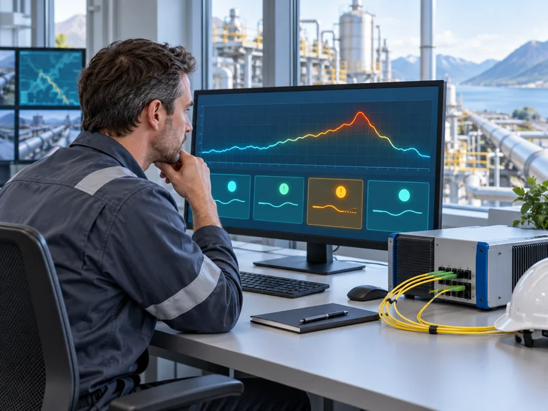
A short hotspot can read lower than its actual peak temperature in a distributed temperature sensing fiber optic system because the instrument has a finite spatial response. The reported value may include contributions from cooler fiber beside the heated section. Evaluate hotspot length, cable placement and thermal contact together before deciding whether a low reading indicates a fault.
This issue is important when using fiber optic temperature monitoring around compact heat sources. A continuous temperature profile does not mean that every tiny object along a route is measured independently. The installation must translate the thermal event of interest into a detectable condition along the sensing fiber.
Why Does the Length of the Heated Section Matter?
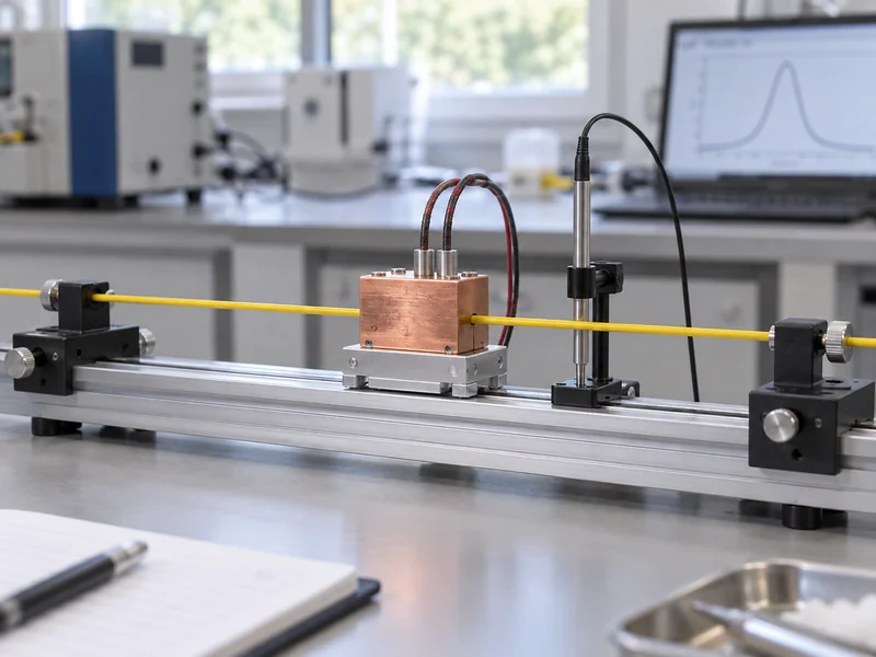
The instrument cannot resolve an infinitely short temperature change. Its spatial response describes how a localized change appears in the reported profile. When the heated length is small relative to that response, the displayed peak can be reduced and broadened.
This is a measurement effect, not necessarily a failure of the optical cable or interrogator. The same maximum physical temperature can produce different profiles when the exposed fiber lengths differ. A long heated coil and a short heated straight section therefore answer different performance questions.
Is Sample Spacing the Same as Spatial Resolution?
No: sample spacing describes the distance between reported output positions, while spatial resolution concerns the ability to distinguish changes along the fiber. A display can contain many closely spaced values without resolving equally short independent thermal features. Increasing the number of plotted points does not remove the underlying spatial response.
The EPA’s technical description of fiber optic DTS explains that spatial and temporal integration influence the measurement. For a project specification, ask the supplier how spatial resolution is defined and demonstrated in the chosen operating mode. A sample-spacing figure alone cannot establish the minimum hotspot length that will trigger an alarm.
Does the Fiber Experience the Same Temperature as the Hotspot?
Not necessarily: the instrument measures the sensing fiber, which may be separated from the source by cable layers, insulation or air. The source can be hot while the fiber remains cooler, particularly during a changing condition. Spatial averaging and incomplete thermal transfer can occur at the same time.
For example, a small heated component near a sensing cable may influence only a short section and may transfer little heat to it. A low DTS peak could then reflect both limited exposure and the cable’s location. The correct response is to investigate the measurement arrangement rather than immediately apply a numerical correction.
| Observed Pattern | Possible Explanation | Useful Check |
| Low, broad peak over a short source | Finite spatial response | Compare approved heated lengths with unchanged settings |
| Delayed rise despite stable source heating | Thermal transfer or cable construction | Compare local reference and DTS trends over time |
| Peak shifted from the expected asset | Optical-distance mapping error | Check lead fiber, slack and route landmarks |
| Unexpected changes after a repair | Altered loss, length or mounting | Review repair records and repeat targeted verification |
These patterns are diagnostic clues, not unique signatures. More than one cause can produce a similar trace. Preserve the original settings and investigate one controlled change at a time.
How Should a Representative Hotspot Test Be Designed?
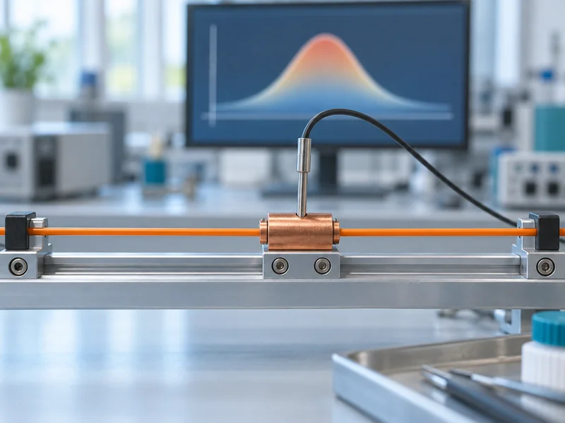
Define the physical condition that matters before selecting the test fixture. Specify the source geometry, exposed fiber length, mounting arrangement and independent reference measurement. Then test the installed or representative cable construction with the acquisition and alarm settings proposed for service.
A supplier demonstration using a conveniently long heated section may establish that the system responds to sustained distributed heating. It does not automatically verify response to a compact source. Ask for evidence that matches the relevant exposure rather than requesting an impressive peak on screen.
- Identify whether the objective concerns surface heating, ambient heating or another thermal quantity.
- Record the actual fiber length exposed to the controlled condition.
- Keep adjacent fiber conditions documented and reasonably stable.
- Use a reference measurement positioned to answer the same thermal question.
- Preserve the profile, timestamps and alarm events for each trial.
Use an approved method that respects the asset and cable limits. A representative fixture may allow safer and more repeatable comparisons than applying heat to operating equipment. For practical context, the existing guide to temperature monitoring for cable-fire prevention explains the wider monitoring objective.
Should Several Heated Lengths Be Compared?
Yes, when the project needs to understand sensitivity to source size and the test can be performed repeatably. Compare lengths relevant to the application while keeping the reference condition, mounting and settings controlled. The resulting profiles show how this particular arrangement responds.
Do not turn a few demonstration points into a universal correction curve without a validated model. A different cable construction, contact condition or integration setting may change the relationship. Report the tested conditions and leave unsupported conditions clearly outside the claim.
Can Coiling the Fiber Improve Local Hotspot Detection?
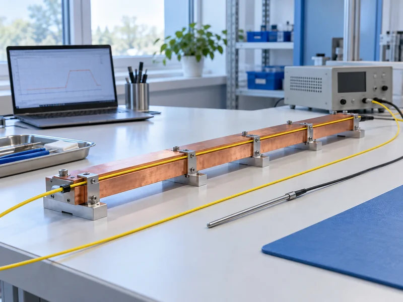
Routing more sensing fiber around a target can increase the exposed optical length, but it changes the installation and must be engineered for the application. The cable still needs adequate thermal coupling and acceptable bend radii. More fiber in the vicinity is not useful if most of it remains thermally isolated from the relevant source.
A coil also changes the relationship between optical distance and physical location. Multiple reported positions may correspond to the same small asset area. The route map and alarm labeling must explain that relationship so operators do not interpret the coil as a long physical corridor.
Check whether an alternative sensor arrangement better matches the target. The comparison of point and distributed temperature sensors is relevant when the requirement centers on a small, precisely defined location. Continuous route coverage and local point measurement can serve different purposes within a wider monitoring design.
Should the Alarm Threshold Be Lowered to Compensate?
Not without evaluating normal operating variation and the resulting alarm behavior. Lowering a threshold may make a short-source demonstration trigger sooner, but it can also increase alarms during ordinary temperature changes. It does not correct the spatial or thermal measurement relationship.
First determine whether the sensing arrangement can distinguish the event from expected conditions with adequate margin. Then evaluate supported alarm rules against representative normal and abnormal data. If the signals are not sufficiently distinguishable, changing the physical arrangement may be more useful than progressively lowering thresholds.
What About Rate-of-Rise Rules?
A rate-of-rise rule can answer a different question from an absolute-temperature rule, but its usefulness depends on the actual thermal and acquisition response. Averaging and cable lag can influence the observed rate. The rule should be verified with representative changes rather than assumed to recover every short hotspot.
Review reset behavior and persistence as well as activation. An alarm that repeatedly switches state around a threshold may be difficult to operate even if one trial meets the detection objective. Keep the reasoning and configuration together in the acceptance record.
What Information Should Be Requested from a DTS Supplier?
Request the spatial-response definition, relevant test conditions and performance under the proposed settings. Explain the smallest thermal region that matters and how the sensing cable will be mounted. This gives the supplier an engineering problem to evaluate instead of a request for a single favorable number.
- Describe the asset, expected thermal exposure and relevant source length.
- Provide the intended sensing-cable construction and mounting details.
- Specify route length, channel use and acquisition settings.
- Agree on a controlled comparison and an independent reference.
- Define the alarm behavior that counts as a successful result.
- Retain limitations and unresolved conditions in the handover.
For underground cable-gallery monitoring, these details help align continuous coverage with the actual thermal risks. The objective is a useful warning under agreed conditions, not a visually sharp graph. A smooth temperature trace can still be useful if its meaning and limits are understood.
When results do not match expectations, use the guide to common DTS problems to structure the investigation. Check physical exposure, spatial response and mapping before declaring a sensor inaccurate. That sequence produces a more defensible decision about whether to adjust the installation, configuration or monitoring method.