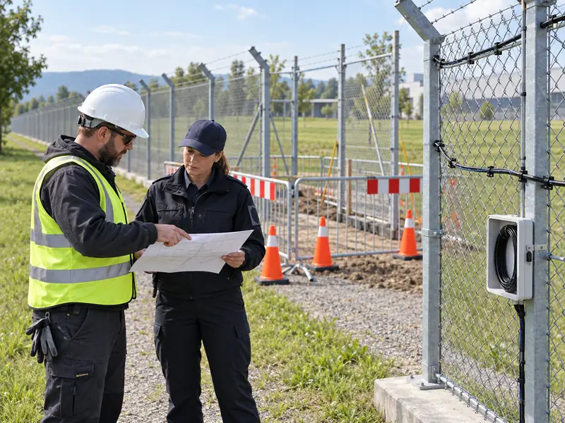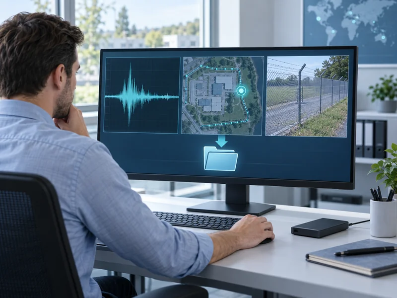

Verify mechanical coupling in distributed acoustic sensing fiber optics by comparing repeatable, authorized test events at known locations while recording the cable attachment, surrounding structure and system settings. An intact optical path does not prove that useful vibration reaches the sensing fiber. The objective is to demonstrate consistent event transfer under the proposed installation conditions.
A DAS perimeter intrusion detection system depends on both optical measurement and the physical path carrying disturbance to the fiber. That path can include soil, fence mesh, brackets, cable sheath and internal cable components. A weak result should therefore prompt a structured physical investigation before repeated sensitivity adjustments.
What Does Mechanical Coupling Mean in a DAS Installation?
It describes how a disturbance in the monitored environment produces strain in the sensing fiber. The fiber does not automatically experience every movement occurring nearby. Cable construction, mounting and the material between source and cable influence that transfer.
The Fiber Optic Sensing Association’s installation guidance identifies cable location and installation method as major contributors to acoustic or vibration coupling. This explains why two routes with similar optical loss can have different sensing behavior. Optical qualification and mechanical qualification answer different questions.
Does a Clear Optical Trace Prove Good Coupling?
No: an optical trace can support checks of continuity, loss and distance, but it does not demonstrate that the target disturbance transfers adequately into the fiber. A cable can be optically sound yet physically isolated from the relevant structure. Conversely, a well-attached cable still needs acceptable optical performance.
Use both kinds of evidence and keep their conclusions separate. The existing guide to qualifying existing fiber for DAS provides the broader retrofit context. This article focuses on the physical transfer that remains to be demonstrated after a route appears optically suitable.
Which Installation Details Should Be Recorded First?
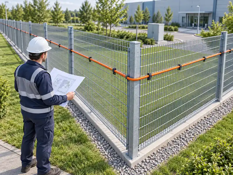
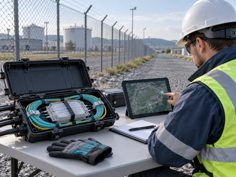
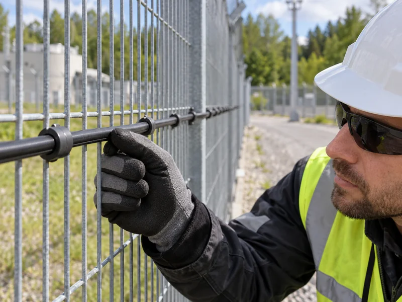
Record the cable model, attachment method, support condition and test location before collecting a baseline. For a fence, note mesh type, panel condition, posts and nearby structural transitions. For a buried route, document the known installation arrangement and relevant ground conditions without assuming that all sections are equivalent.
| Route Feature | Why It Matters | Evidence to Keep |
| Attachment | Loose or inconsistent mounting changes transfer | Photographs and approved installation detail |
| Support Structure | Different panels or materials respond differently | Panel type and condition record |
| Cable Construction | Internal components influence strain transfer | Manufacturer identification |
| Local Environment | Background activity affects interpretation | Time, weather and nearby operations |
| System Configuration | Processing changes alter the comparison | Configuration version and active zone |
Do not compensate for missing installation records by assuming a uniform cable route. Mark uncertainty explicitly and investigate the sections that control the acceptance decision. A short, well-documented comparison is more useful than a long test sequence with unknown mounting conditions.
How Should Test Events Be Made Repeatable?
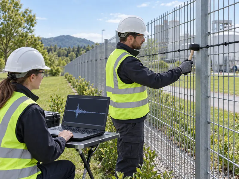
Use an approved, non-destructive event method with a defined location and procedure. Repeat it under reasonably similar conditions and retain the corresponding system evidence. The test should resemble the disturbance the project needs to detect closely enough to answer the engineering question.
A convenient tap may demonstrate that some vibration reaches the fiber, but it does not automatically validate every required intrusion behavior. Describe what the test represents and what it does not. More demanding acceptance events should follow the site’s authorized test plan and safe working arrangements.
What Should Stay Constant During a Comparison?
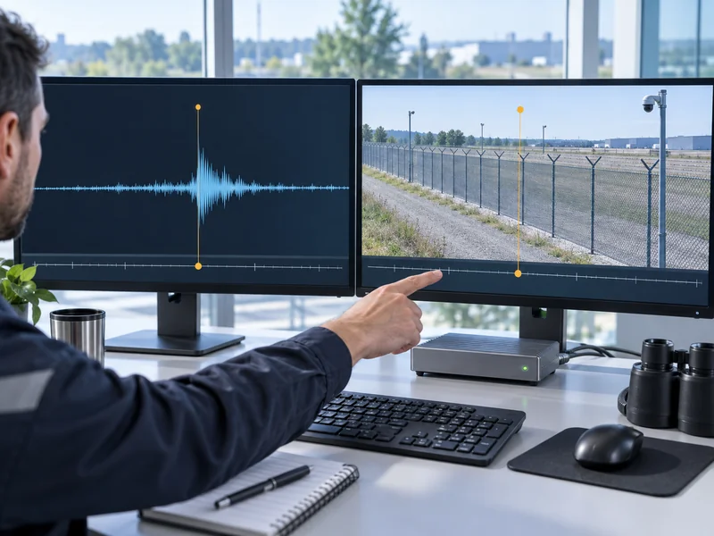
Keep the event method, source position and active processing settings constant when evaluating an attachment change. If these factors change together, a stronger signal cannot be attributed confidently to improved coupling. Preserve the baseline before making an adjustment.
- Use the same marked event location and agreed procedure.
- Record the operator and relevant differences in execution.
- Retain the configuration version used for each trial.
- Document the physical change with before-and-after photographs.
- Repeat enough trials to reveal obvious inconsistency rather than selecting only the strongest response.
The precise number of trials should come from the project plan, not a universal count. A single successful alarm is weak evidence of repeatable behavior. Include unsuccessful and ambiguous outcomes in the record so the final decision reflects the whole comparison.
Which Mounting Changes Preserve the Sensing Cable’s Limits?
Follow the sensing-cable and system supplier’s approved installation detail. Excessive tightening can damage a cable even if it initially increases the apparent response. The goal is a durable, controlled attachment rather than maximum mechanical pressure.
Check unsupported spans, displaced fixings and changes in the supporting structure. A repaired fence panel may require a different review from a cable that has simply slipped from its original position. Address the cause while preserving bend, tensile and environmental limits.
The F7 installation and commissioning guide is a relevant starting point for a Gato project. Obtain the current project-specific detail where the public guide does not resolve the mounting condition. Do not apply another manufacturer’s fixing interval without checking suitability.
How Should Buried and Fence-Mounted Results Be Compared?
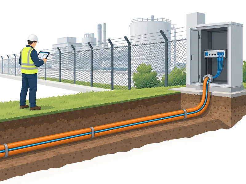
Treat them as different physical arrangements with different event-transfer paths. A fence test excites a structure, while a buried-cable test depends on how disturbance reaches the cable through the surrounding ground and installation. Equal software settings do not make the measurements directly interchangeable.
For a buried route, variations in ground conditions or cable containment can influence the response. For a fence, support stiffness and mesh condition can vary along the perimeter. Divide the evaluation into representative sections and explain the basis for grouping them.
Can a Strong Response in One Section Validate the Whole Route?
Only if there is a justified basis for considering the other sections equivalent, and the acceptance plan permits that approach. Structural transitions, route changes and different installation methods deserve separate attention. Test coverage should follow the differences that matter physically.
As an illustrative example, a perimeter may combine rigid welded panels with a separate chain-link section. A successful comparison on one panel type would not by itself validate the other. The record should identify both arrangements and the evidence supporting each.
What If a Better Signal Still Produces No Useful Alarm?
Investigate detection and classification separately from mechanical transfer. A visible response may not meet the configured event criteria, and a background disturbance may produce a large signal without representing the target event. Coupling improvement is one part of the detection chain.
Review the event record with the supplier using the documented physical conditions and settings. Avoid increasing sensitivity across the entire route to address one local installation defect. That can change the nuisance-alarm behavior elsewhere without resolving the original cause.
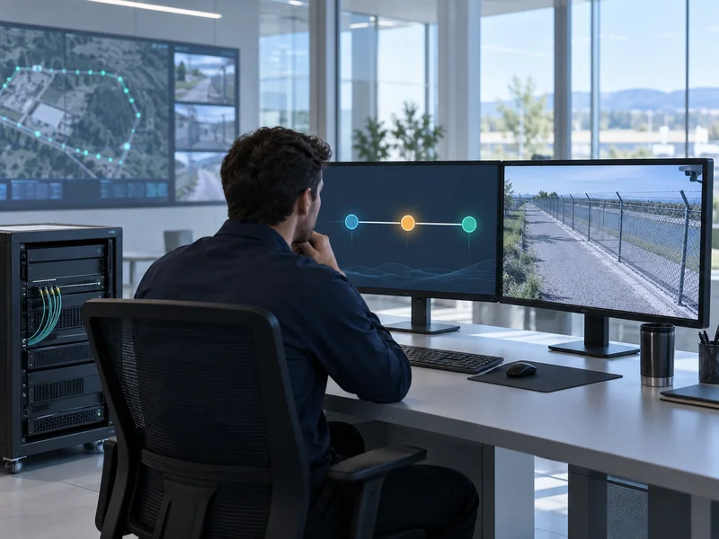
Where centralized alarm management is used, confirm that the source event reaches the correct zone and operator view. A valid sensor response can still be operationally ineffective if mapping or event delivery is wrong. Keep those findings distinct from the coupling assessment.
What Should Be Accepted and Handed Over?
Accept the documented installation and its repeatable behavior under the agreed test conditions. Record unresolved sections, physical changes and any configuration changes that followed. The handover should let maintenance staff recognize when a future repair has altered the verified arrangement.
- Identify the tested route sections and their installation types.
- Retain baseline and final photographs.
- Store test-event records with configuration versions.
- Document unsuccessful trials and corrective actions.
- Assign responsibility for retesting after relevant physical changes.
Use the broader perimeter system acceptance checklist to connect these findings to the whole security workflow. Mechanical coupling verification demonstrates that the route can carry useful disturbance information to the fiber. Final acceptance also needs the detection, location and operator-response functions to work together.