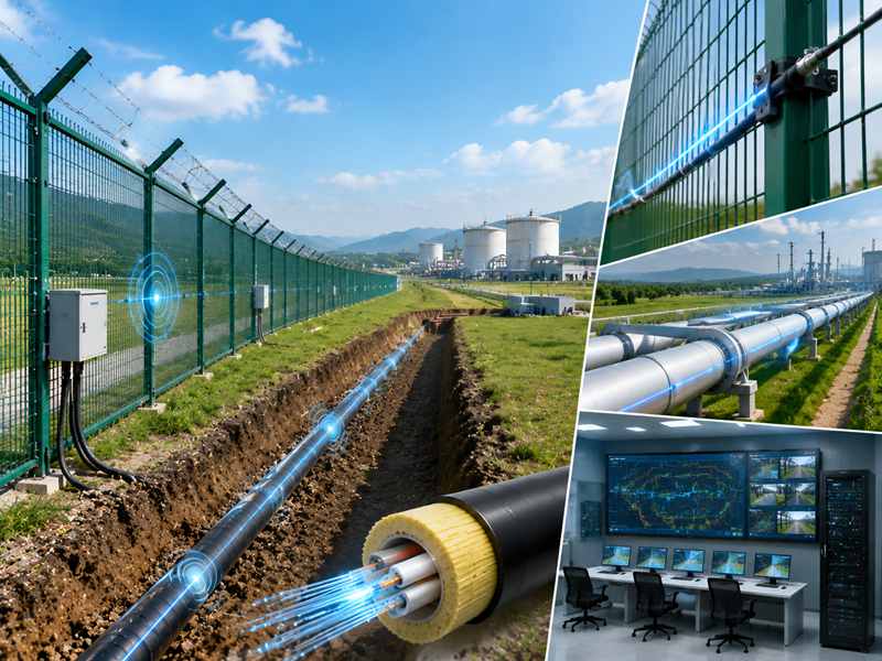
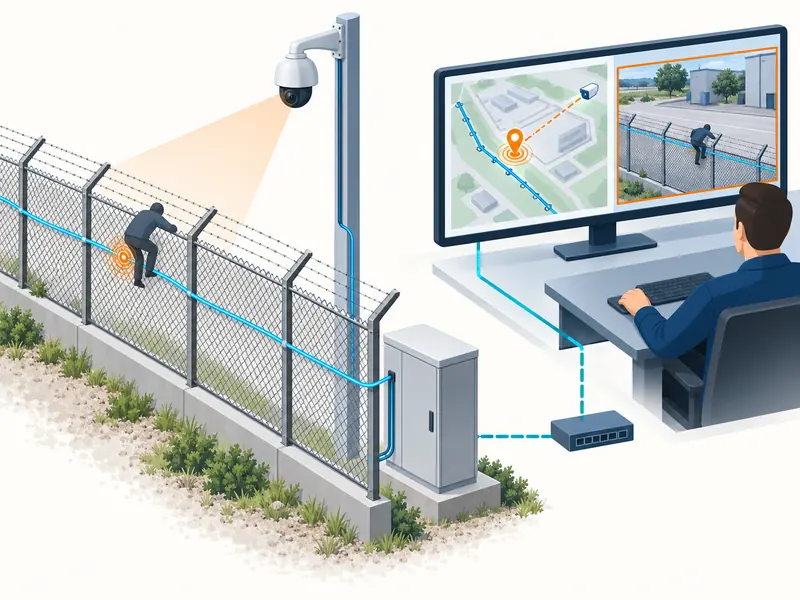
A DAS alarm becomes more useful when the operator can immediately see the relevant location, open the right video and record a response. Connecting equipment is only part of that result. The integration must also preserve the meaning of the event as it moves between systems.
This guide presents a practical design for DAS, CCTV, a video management system and geographic mapping. It focuses on the information and tests that make an integrated perimeter system usable after commissioning.
What should happen when DAS detects a perimeter event?
Direct Answer: The agreed workflow should deliver an identifiable alarm, a mapped location and the appropriate camera view, then let the operator acknowledge, investigate and close the event with a traceable record.
Explanation: Write the workflow before choosing an interface. Start with a representative event at a named fence section. Describe what appears on screen, which camera is selected, whether a preset moves, and where the operator records the outcome.
Our view is that an integration specification should read like a short operating procedure. The phrase “CCTV linkage” needs a list of observable actions before it can guide commissioning. It could mean a video stream is visible, a camera is called automatically, or a full alarm lifecycle is synchronized. Those are different deliverables.
Separate automatic actions from human decisions. Opening the relevant view can help verification, but the event label should not silently become a confirmed intrusion. The operator needs to distinguish sensor classification, visual evidence, and the final disposition.
Also decide what should happen when a second alarm arrives. A moving camera cannot always serve two locations at once. Priority rules, alternative views and an alarm queue make that limitation manageable.
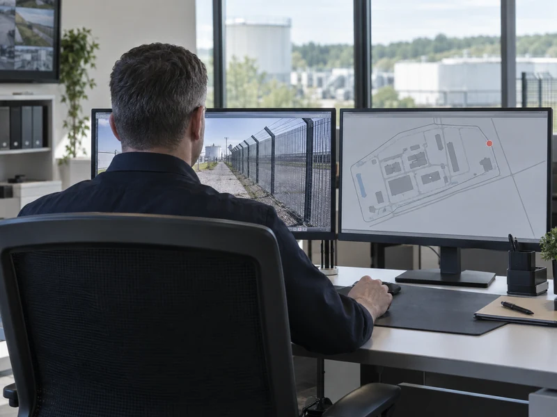
Conditions: The site must define event categories, operator roles and response priorities. Include out-of-hours operation and cases where the expected camera is unavailable.
Evidence: Gato’s SAM300 describes GIS and video-alarm linkage functions. For a particular project, request a demonstration of the exact workflow with the intended camera and software versions.
Related Article: Review the SAM300 security management platform as the product-level starting point for those discussions.
Does ONVIF or RTSP support guarantee complete integration?
Direct Answer: No. A supported video connection does not by itself establish alarm exchange, camera selection, acknowledgment synchronization or reliable recording association. Confirm each required function separately.
Explanation: Start with an interface matrix listing the source system, destination system, function, supported version, and test method. This prevents a familiar protocol name from standing in for an agreed scope.
For example, displaying a camera stream and moving that camera to a preset are different functions. Associating a DAS event identifier with recorded footage is another. A working image on a monitor proves only the part that was actually demonstrated.
Record the tested combination as a repeatable configuration, with the versions and settings needed for commissioning. Record camera model, firmware, VMS version, driver or connector version and license requirements. Keep that record with the configuration backup.
| Integration function | Question to resolve | Acceptance observation |
| Video display | Can the client open the supported stream? | Usable live image |
| Camera positioning | Can the selected preset be invoked? | Correct fence section visible |
| Alarm exchange | Which event fields are delivered? | Correct identifier, time and location |
| Event history | Can the operator retrieve associated evidence? | Matching record and footage |
Conditions: Verify supported features for both device and client. Do not assume that every optional feature is implemented, or that a third-party connector includes all functions available in a manufacturer’s own software.
Evidence: ONVIF Profile T defines video-related features and distinguishes mandatory from conditional capabilities. Its scope does not replace a project-specific demonstration of the full DAS alarm workflow.
Related Article: Check the distributed acoustic sensing fiber optics for available integration options, then verify the proposed combination.
How should fiber distance map to cameras and GIS locations?
Direct Answer: Build a surveyed relationship between fiber positions, physical landmarks and camera coverage. Treat that relationship as maintained configuration, not a one-time drawing.
Explanation: DAS reports activity along its sensing path. The security team responds to a gate, road or fence sector. Lead-in cable, spare loops and detours can make the relationship between optical distance and physical distance uneven.
Use identifiable reference points to establish mapping. Then test locations between those references, particularly where the route changes direction or installation method. A correct pin at each endpoint does not prove that every intervening point is correctly represented.
Camera assignment should reflect useful visibility. The physically nearest camera may face the wrong direction, have an obstructed view, or provide insufficient detail at night. Assign a primary view and, where justified, an alternative that covers the same alarm area.
Our recommended unit of design is the verification area: the part of the perimeter that a specific view can assess effectively. Align alarm rules with those areas while preserving the event’s finer location information where available.
Document how overlapping coverage is handled. A boundary alarm may reasonably call two views rather than force an artificial one-camera choice. The operator should understand why those views were selected.
Conditions: Define coordinate reference information, map ownership and update responsibilities. Recheck the relationship after cable repairs, fence changes, camera relocation or preset adjustments.
Evidence: Retain a mapping register with reference locations, fiber distances, camera identifiers and tested presets. Walk-test representative positions and compare the displayed pin with the actual site location.
Related Article: Our DAS installation conditions guide explains why the physical route must be understood before commissioning.
What alarm data and failure behaviour should be specified?
Direct Answer: Define a stable event identifier, event time, source, location, category and state. Also specify how each system reports lost connectivity, unavailable cameras and recovery after interruption.
Explanation: Without consistent identifiers, one physical incident can appear as unrelated records in the DAS interface, VMS and incident log. Without a common interpretation of timestamps, video retrieval may open the wrong period even though every system seems to be working.
Agree which system owns acknowledgment and closure. An operator acknowledging an alarm in the management platform may or may not clear it in the source application. That behaviour should be deliberate and visible.
Our design preference is to distinguish event delivery from operator presentation. A received event should be recorded even if its camera view cannot open. The interface should show that limitation instead of making the underlying alarm disappear.
- Define required fields and permitted missing values.
- Specify time synchronization and timestamp interpretation.
- Agree duplicate-event handling and queue behaviour.
- Show communication failure separately from an intrusion alarm.
- Define what happens to queued events after reconnection.
- Limit integration accounts to the functions they need.
These requirements make troubleshooting more concrete. When an operator reports a missing view, the team can determine whether the event was generated, transmitted, mapped or displayed incorrectly.
Conditions: Use supported interfaces and document credentials ownership, network paths and change procedures. Do not assume an offline queue exists unless the selected product and connector actually provide it.
Evidence: Ask for a sample event payload or interface specification, then compare it with the fields visible in a controlled test. Interrupt the relevant connection through an approved test procedure and record both failure indication and recovery behaviour.
Related Article: Our DAS procurement guide helps turn these integration requirements into supplier questions.
How do you prove the integrated system is ready for operation?
Direct Answer: Run end-to-end scenarios from a controlled field event through operator action and evidence retrieval. Test normal operation, simultaneous alarms and agreed failure cases before handover.
Explanation: A successful connection test establishes that two systems communicate. A successful operating test establishes that the security team can use the result. Both are necessary, but they answer different questions.
Begin with several locations across the perimeter. For each event, record the physical action, alarm creation time, displayed location, camera view and operator disposition. Use the same event identifier to trace the path through the systems.
Then introduce realistic complexity. Trigger two separate events, make one camera unavailable under a controlled procedure, or test after an approved network interruption. Confirm that operators can recognize the degraded condition and follow the intended alternative.
Our recommendation is to measure time to useful verification rather than celebrating the first pop-up. A fast alarm that opens an irrelevant view still leaves the operator searching. The acceptance discussion should include the complete task.
Finish with a handover package containing the interface matrix, mapping register, configuration backups, version record and recovery instructions. Assign responsibility for retesting when any linked system is upgraded.
Include day and night verification where lighting changes the camera’s usefulness. Keep test expectations specific: a visible event marker, a usable image and a retrievable record are separate observations, and each should have its own result.
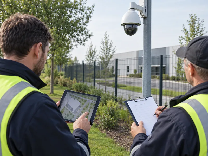
Conditions: Agree acceptable timing and outcomes before the test. Use safe, authorized field actions, and avoid disruptive failure tests on a live operational system without the site’s planned maintenance procedure.
Evidence: Retain event logs, screenshots, and retrieved video references alongside the signed test results. These provide a reproducible baseline for later fault investigation and software changes.
Related Article: Use our perimeter system acceptance checklist to structure the final operational demonstration.