


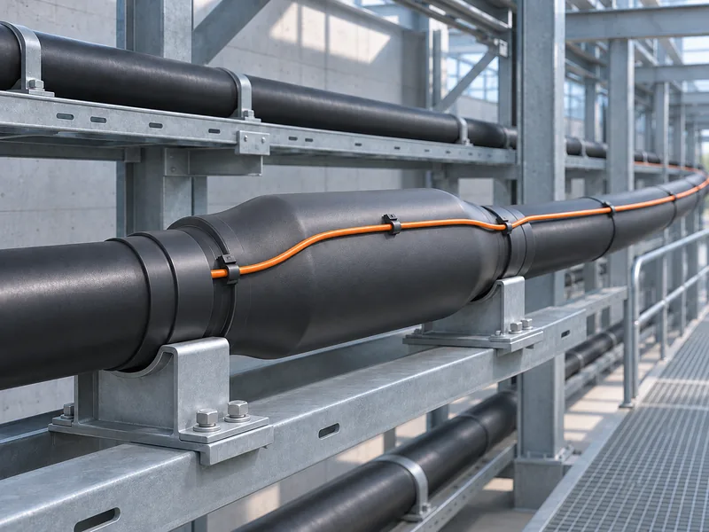
Cable joint temperature monitoring should connect each measured location to an identifiable joint and a clear maintenance response. Start with the joint register, define the thermal condition to be observed, and verify that the proposed sensing arrangement can detect it. Configure alarms only after the installation and operating context are understood.
Distributed temperature sensing can support this work by measuring temperature along a sensing fiber. For joint monitoring, the planning challenge is making that continuous profile useful at specific assets. A temperature trace needs an accurate location, a meaningful baseline and an assigned response.
Begin With a Cable Joint Register
Create a register of the joints included in the project. Give each joint a stable identifier that matches the site drawing and maintenance system. Record the cable circuit, physical location, access conditions and available construction information.
Separate confirmed information from assumptions. A drawing may show where a joint should be without proving its present arrangement or accessibility. Resolve those uncertainties before committing to a sensing cable route.
Include existing maintenance concerns where records are available. Previous inspections, repairs and operating observations can help define what the monitoring project needs to investigate. Do not turn an undocumented concern into a claimed failure history.
The register should remain useful after installation. If a joint is replaced or relocated, the monitoring label and maintenance record need to change with it.
Define the temperature that matters
Specify whether the project seeks to observe a joint surface, the surrounding environment or another accessible thermal condition. These are different measurement objectives. A sensing cable placed near a joint does not automatically measure the temperature inside it.
Describe how heat is expected to reach the sensing fiber. The joint structure, outer covering and installation arrangement influence that relationship. Ask the supplier to review the proposed mounting detail against the actual equipment information.
Gato’s E3 distributed temperature sensing system identifies cable joints as an application for its centimeter-level configuration. The page lists temperature accuracy as precise as ±0.5°C for that model and a monitoring distance of up to 2.5 km per channel.
Those specifications help frame a product discussion, but they do not establish the temperature inside every joint. Confirm the selected configuration and measurement conditions before using a specification as an acceptance requirement.
Plan Coverage Around Individual Assets
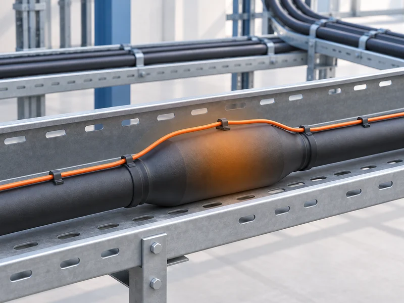
Decide which joints require dedicated identification and which adjoining cable sections should also be monitored. A route that passes through an area may provide useful surrounding information while still requiring a specific arrangement at a compact joint.
Review the proposed fiber path with the equipment owner. Mounting must respect access, maintenance requirements and the equipment manufacturer’s restrictions. Avoid selecting a convenient attachment point before confirming that it represents the intended thermal condition.
Use a coverage schedule to make these decisions explicit.
|
Planning field |
Information to record |
Why it matters |
|
Joint identity |
Asset label and cable circuit |
Connects the alarm to maintenance records |
|
Physical position |
Drawing reference and access route |
Helps staff locate the correct joint |
|
Monitoring objective |
Surface or surrounding thermal condition |
Defines what the reading represents |
|
Sensing arrangement |
Approved cable path and mounting detail |
Makes installation review possible |
|
Operating context |
Available load and ambient observations |
Supports interpretation of temperature trends |
|
Response owner |
Responsible team and escalation route |
Converts a warning into an assigned action |
Keep the schedule focused on installed assets. Future joints can appear in a separate expansion plan without being represented as monitored locations.
Verify Local Thermal Response Before Setting Alarms
A compact heat source needs a representative evaluation. Confirm that the proposed sensing arrangement responds to the thermal condition the project cares about. A demonstration using a different cable placement may not answer that question.
Use the supplier’s approved test approach and record the arrangement. The test record should identify the sensing cable, mounting, acquisition settings and reference measurement. Any variations between the demonstration setup and the installed joint should remain clearly visible.
Gato’s explanation of DTS hotspot length and short heat sources provides the relevant measurement background. Use that guidance when reviewing a local hotspot requirement, while keeping the joint project focused on coverage and maintenance decisions.
Avoid treating a favorable graph as proof of every operating condition. Acceptance should describe what was tested and which conclusion the result supports.
Make Optical Positions Recognizable to Maintenance Staff
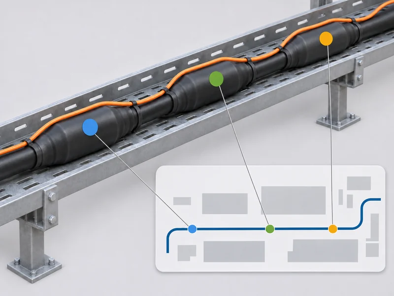
The monitoring system reports positions along an optical path. Maintenance staff work with circuit names, joint identifiers and access locations. The project needs a documented relationship between those references.
Prepare the location map after the cable route and connections are established. Identify installed reserve, connection sections and other portions that do not correspond directly to additional assets. Otherwise, an apparent distance along the fiber can be mistaken for a physical distance along the cable circuit.
Check the map using known locations and the approved verification method. Confirm that the displayed alarm points to the correct joint, rather than merely appearing somewhere nearby. Keep the results together with the final installation drawing.
Use consistent labels across the monitoring display, site signage and maintenance records. A technically accurate measurement becomes harder to act on when the same joint has different names in different systems.
Develop Alarms From the Operating Context
Alarm settings should reflect the monitored asset and the purpose of the warning. Gather representative operating observations before deciding how a change should be interpreted. Where load information is available, retain it alongside the temperature record.
Distinguish a developing temperature concern from a sensing-system fault. An unavailable measurement should not appear to operators as a normal joint temperature. Define separate response instructions for the conditions supported by the delivered system.
For each alarm, document:
- The joint or monitored section to which it applies.
- The condition that activates the warning.
- The information the operator should review.
- The team responsible for inspection or escalation.
- How acknowledgment and return to normal are handled.
- What records should be retained after the event.
Avoid publishing a universal joint alarm temperature. The appropriate setting depends on the equipment, measured thermal quantity and approved operating requirements. Obtain the relevant limits from the equipment owner and supplier.
Connect the Warning to a Maintenance Decision
A useful alert should help the operator decide what to do next. The initial review can confirm the asset identity, examine the recent trend and check for known operating changes. It should also establish whether the measurement channel is functioning normally.
The maintenance team then follows the site’s approved inspection and response procedure. A temperature indication alone does not identify every possible cause of heating. Record findings before deciding whether a configuration change or equipment intervention is appropriate.
Preserve the event context. Include the reported location, timing, trend and any relevant operating observations. When staff take corrective action, record what changed and how the monitored condition behaved afterward.
This creates a practical history for the joint. Over time, staff can distinguish recurring operating patterns from changes that deserve investigation, using actual records rather than assumptions about normal behavior.
Build Acceptance Around the Installed Arrangement
Commissioning should verify the chain from sensing location to maintenance response. Confirm that the approved fiber route was installed, the position map is correct and the expected information reaches the operator.
Prepare an acceptance checklist that covers:
- Joint labels matched to the final asset register.
- Optical continuity and connection records.
- Approved mounting details and installation photographs.
- Representative response verification at agreed locations.
- Correct warning and fault indications.
- Alarm acknowledgment and event record retrieval.
- Maintenance access and responsibility for future changes.
Use the proposed operating settings during relevant tests. If the settings change afterward, review which checks must be repeated. Retain unsuccessful tests and corrective actions so the final record explains how the accepted arrangement was achieved.
A general sensor specification cannot replace these installation checks. The project needs evidence that its own joints, labels and response workflow have been addressed.
Keep Monitoring Records Current After Repairs
Joint replacement, cable work and sensing-fiber repairs can alter the monitoring arrangement. Treat each relevant intervention as a reason to review the associated records. Even an intact temperature trace may require a location or mounting check.
Before work begins, preserve the current drawing and configuration references. Identify affected assets and agree how any temporary monitoring limitation will be handled. After the intervention, confirm that the intended coverage has been restored.
Update the joint register, installation photographs and location map together. Record any revised alarm settings and the reason for the change. This prevents a later investigation from relying on a configuration that no longer matches the site.
Prepare a Focused DTS Project Enquiry
A cable joint temperature monitoring enquiry should describe the assets and the decision the monitoring will support. Provide the joint register, construction details, route drawing and access restrictions. Include existing operating records when they are available and relevant.
Ask the supplier to explain the proposed sensing arrangement, configuration and verification method. Request a clear distinction between published instrument capability and performance that still requires confirmation on the installation.
An effective project delivers identifiable measurements and a usable maintenance process. With the joint register, coverage schedule and response records aligned, temperature monitoring can become part of routine asset management rather than an isolated display.





How Can We Help?
Please describe your request and how we can help.