


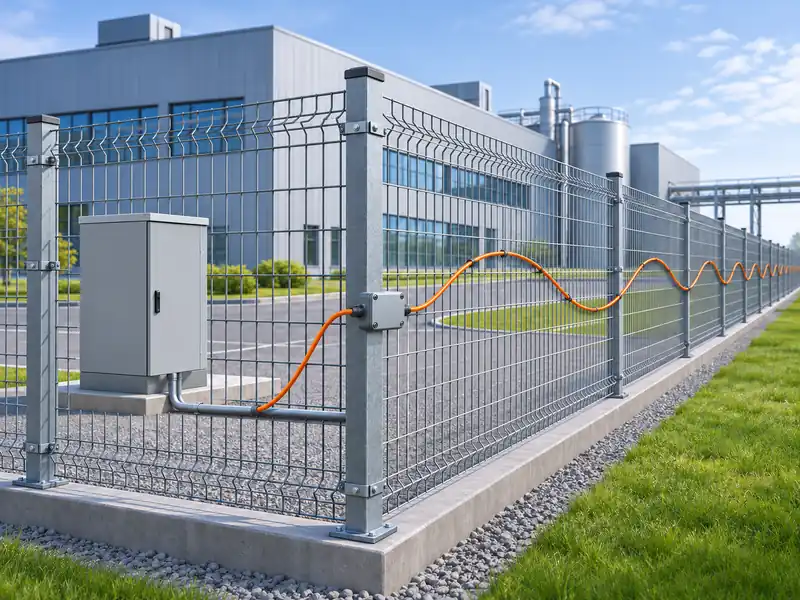
Calculating sensing cable length for a DAS perimeter project starts with the installed route. Measure each sensing section, account for its routing pattern, and add the connections and reserves required by the approved design. Keep the protected boundary length separate from the cable quantity being purchased.
This distinction matters before requesting quotations. A perimeter drawing shows where protection is needed, but it may omit vertical transitions, equipment-room connections, gate crossings and stored cable. An accurate quantity schedule makes these differences visible to the designer, installer and buyer.
Define what each length represents
Protected perimeter length describes the boundary that the project intends to monitor. Installed cable length describes the physical cable following the approved route. Optical path length describes the fiber path seen by the interrogator, which also depends on how the fibers are connected.
These quantities can differ without indicating a mistake. A wave-pattern installation uses more cable than a straight route along the same fence. A lead-in section consumes cable and optical distance even when it does not provide the intended fence monitoring function.
Use separate fields for these quantities throughout the project. Avoid changing the meaning of length between a site drawing, supplier quotation and commissioning record. Where the supplier uses a different definition, ask for the relationship to be explained before comparing offers.
Survey the route before calculating quantities
Begin with the current site plan and confirm the proposed route on site. Record where the sensing cable follows the fence, changes height, passes an entrance or connects to another installation method. Measure the actual path around obstructions instead of using a straight line across them.
The equipment location also matters. A cabinet near the perimeter requires a different lead-in arrangement from a control room reached through an internal service route. Include that connection in the survey even when another contractor supplies it.
Collect the following information:
- Fence section identifiers, physical lengths and construction types.
- Approved straight, wave-pattern or buried routing details.
- Gate crossings, elevation changes and transitions between surfaces.
- Host location, entry points and proposed connection routes.
- Splice enclosure positions and maintenance access requirements.
- Areas where the route or monitoring responsibility remains unresolved.
Mark uncertain sections on the drawing. A measured quantity and a provisional allowance should remain distinguishable until the route has been confirmed.
Measure straight and wave pattern sections differently
For straight sections, follow the cable support path rather than simply copying the horizontal boundary dimension. Include actual changes in direction and height. Count a transition once, using a clear start and end point.
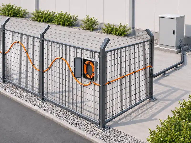
For wave-pattern sections, determine the cable required for the approved pattern. A representative installation detail or measured trial section is more useful than an assumed multiplication factor. The pattern geometry must match what the installer will build.
Gato’s F7 installation and commissioning guide describes straight and wave-type fence routing. Use the relevant installation detail when preparing the quantity schedule, while confirming the current project requirements with the supplier.
Apply a measured routing allowance only to sections using that arrangement. If the perimeter combines different fence structures or installation methods, calculate them separately. A single factor applied to the entire site can hide the sections responsible for additional cable.
Build a cable quantity schedule
Organize the calculation by physical section and cable type. This allows the installer to check the route and lets procurement distinguish sensing cable from communication cable, jumpers and accessories. Items with different specifications should not disappear into a single total.
The following schedule shows what to record before entering quantities.
|
Route item |
Measurement basis |
Review point |
|
Straight sensing section |
Actual supported cable path |
Include changes in height and direction |
|
Wave-pattern sensing section |
Approved pattern along that section |
Confirm the installed geometry |
|
Buried sensing section |
Surveyed trench and cable route |
Check transitions and route changes |
|
Lead-in connection |
Route between host and sensing area |
Confirm cable type and sensing treatment |
|
Gate or obstacle crossing |
Approved physical crossing detail |
Avoid double counting adjacent sections |
|
Maintenance reserve |
Allowance at identified locations |
Record purpose and storage position |
For each cable type, add the measured installation sections and the approved installed reserves. Record uninstalled spare stock separately. This keeps the purchase quantity understandable without confusing spare material with the operating optical path.
Use consistent measurement units and retain the source of each entry. A drawing measurement, a site measurement and a supplier allowance have different levels of certainty. Keeping those origins visible helps reviewers resolve discrepancies without repeating the entire survey.
Use the published F7 case as a planning lesson
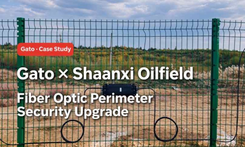
The Gato F7 fiber optic intrusion detection system page describes a refinery installation using approximately 15 km of sensing cable along an 8 km perimeter. This is a documented example of cable length exceeding boundary length.
The case illustrates a key planning consideration: cable order cannot be determined solely by perimeter distance. It does not establish a universal routing multiplier for another site. The public description also does not provide a complete quantity breakdown for reproducing that installation.
For a new project, retain the same distinction between boundary and cable length while calculating from the actual layout. Ask the supplier to identify which routing decisions increase the cable requirement and which sections contribute to useful sensing coverage.
Assign reserves to real locations
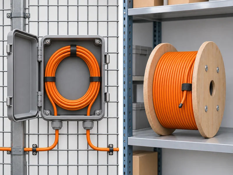
Maintenance reserves should appear at identified points in the design. Record their purpose, cable type and storage arrangement. An unexplained allowance added at the end of a spreadsheet is difficult to inspect and may be duplicated by another contractor.
Distinguish installed reserve from spare cable stored for future repairs. Installed reserve can form part of the optical path. Spare stock that remains on a drum does not extend the current channel or increase the protected boundary.
The public installation guide includes terminal reserve guidance, but the final allowance should follow the selected cable and project detail. Storage must also preserve the cable’s specified bend and mechanical limits.
Avoid adding multiple overlapping contingencies. If a contractor has already included reserves within each section, make that visible before applying any further procurement allowance.
Check the optical path for each channel
The total cable order does not, by itself, determine whether the sensing arrangement fits the selected interrogator. Review the connected optical path for each channel, including lead-ins and installed reserve. A multi-core cable also requires a clear fiber connection diagram.
Gato lists F7 capability of up to 70 km per channel and up to 140 km across two channels. Treat these as published product limits to review against the proposed configuration. They do not mean every route of that length will provide the required detection performance.
Confirm the fiber specification, connections, optical loss and sensing arrangement with the supplier. Additional cable can affect the optical path without adding equivalent physical coverage. The channel schedule should therefore connect each stated distance to its route and installation assumptions.
Turn the calculation into a comparable quotation
Send suppliers the same drawing revision and quantity assumptions. Ask them to identify whether their offer includes cable, connection accessories, installation, splicing and commissioning. A low cable quantity may reflect an omitted route rather than a more economical design.
Request a clear explanation of differences between the buyer’s schedule and the supplier’s calculation. Resolve those differences before placing the order. Otherwise, the project may discover missing material only after installation has started.
The quotation package should include:
- A marked route drawing and section identifiers.
- Quantities separated by cable type and installation method.
- Installed reserves and uninstalled spare material shown separately.
- Channel routes and proposed fiber connections.
- Supplier exclusions and responsibilities for connecting sections.
- A process for approving route changes during construction.
Keep optional future extensions separate from the initial installation. This lets the buyer compare current scope without treating possible expansion as confirmed coverage.
Verify quantities during installation and handover
Record route changes as they occur. Moving a cabinet, bypassing an obstruction or changing the fence routing pattern can alter the required cable length. Update the quantity schedule and channel drawing together.
At handover, reconcile the installed route with cable records and optical measurements. An optical distance reading needs interpretation alongside the connection arrangement and stored reserve. It should not automatically replace the surveyed perimeter measurement.
Check that alarm locations correspond to recognizable site positions. A reserve loop or repaired section can change the relationship between optical distance and physical location. Preserve the final drawing so future maintenance does not begin with an outdated route.
Compile the necessary information for a project review.
A useful cable calculation gives the supplier enough information to review the proposed installation. It identifies where the cable goes, why additional length is needed, and which assumptions remain open.
Before requesting an F7 configuration, assemble the perimeter drawing, routing details, host location and channel plan. Include the required detection functions and access constraints. These inputs support a quantity review that reflects the actual site.
The resulting schedule should be usable beyond procurement. Installers can build from it, commissioning staff can verify it, and maintenance teams can update it after changes. That continuity is what makes the original cable calculation valuable.




How Can We Help?
Please describe your request and how we can help.