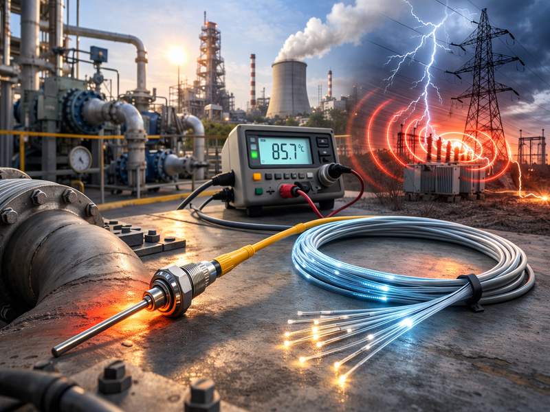
In the power industry, transformer reliability is vital for stable energy distribution. Constant electrical and thermal stress can cause insulation failure or aging if temperatures exceed safe limits. Accurate, continuous monitoring is essential, yet traditional RTDs and thermocouples struggle in high-voltage, oil-filled environments. Fiber optic temperature sensors solve this challenge by using light instead of electricity, offering safe, precise, real-time data even under extreme transformer conditions.
The Role of Temperature Monitoring in Transformers
Temperature is the most important factor affecting transformer performance and lifespan. Every 6–8°C rise above the design limit can halve the insulation life according to IEEE and IEC standards.
Key Monitoring Zones
- Winding hot-spots: Most critical region, often the cause of insulation failure.
- Core and yoke: Affects magnetic losses and oil circulation.
- Oil temperature: Reflects overall thermal behavior and cooling efficiency.
When these areas overheat, it leads to oil oxidation, insulation deterioration, and efficiency loss. Thus, maintaining optimal temperatures ensures transformer longevity, safety, and load efficiency.
What Is a Fiber Optic Temperature Sensor?
A fiber optic temperature sensor is a non-electrical device that measures temperature using light transmission through optical fibers. Instead of relying on electrical resistance or voltage changes, it measures the effect of temperature on light properties such as wavelength, intensity, or fluorescence decay.
Main Components
- Optical Fiber: Carries light signals safely through high-voltage regions.
- Sensing Probes: Placed at strategic points like winding or oil channels.
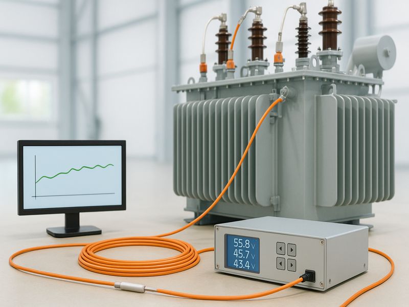
- Signal Conditioner / Interrogator: Converts optical data into temperature readings.
- Display or Data System: Displays data or sends it to the transformer control unit.
Because light is immune to electromagnetic interference and the fibers are non-conductive, fiber optic sensors are intrinsically safe for high-voltage transformer environments.
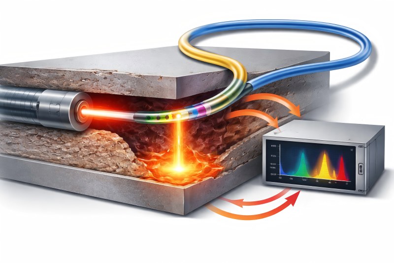
Working Principle of Fiber Optic Temperature Sensors in Transformers
Fiber optic sensors operate based on light interaction with temperature-sensitive materials. In transformer applications, two main technologies are used:
Fluorescence-based Sensors (Fluoroptic®):
These use a temperature-sensitive phosphorescent material at the fiber tip. When illuminated, it emits light that decays over time. The decay rate changes with temperature, allowing precise temperature measurement.
Sensors for Fiber Bragg Grating (FBG):
The fiber core of FBGs is engraved with tiny gratings. As temperature changes, the reflected wavelength (Bragg wavelength) shifts linearly, giving accurate temperature readings.
Simplified Operation Flow
- Light is emitted from the interrogator into the fiber.
- The sensor probe at the target location reflects or re-emits light based on temperature.
- The temperature is ascertained by analyzing the signal that is returned.
- Results are transmitted to the transformer monitoring system in real-time.
This method enables direct, multi-point measurement even inside energized windings—something impossible with electrical sensors.
Advantages of Fiber Optic Temperature Sensors in Transformers
Fiber optic sensors offer transformative benefits over traditional electrical sensors, particularly in oil-filled power transformers.
Key Advantages
- Electrical Isolation: Non-conductive fibers eliminate short-circuit risks.
- Immunity to EMI: No interference from high magnetic fields or switching transients.
- Hot-Spot Accuracy: Direct measurement inside windings where heat originates.
- Safety: Fully safe in high-voltage oil-filled environments.
- Durability: Resistant to oil, pressure, vibration, and high voltage.
- Low Maintenance: No recalibration required over long lifespans.
- Fast Response: Instant detection of temperature rise during load surges.
Fiber Optic vs. Conventional Temperature Sensors
| Feature | RTD / Thermocouple | Fiber Optic Temperature Sensor |
| Signal Type | Electrical | Optical (Light-based) |
| Electrical Conductivity | Conductive | Non-conductive |
| EMI Sensitivity | High | None |
| Measurement Location | External / surface | Directly in winding |
| Accuracy | ±2–3°C | ±0.5°C or better |
| Safety | Risk of electric arc | Intrinsically safe |
| Response Time | Slow | Fast (milliseconds) |
| Maintenance | Frequent calibration | Virtually maintenance-free |
Types of Fiber Optic Temperature Sensors Used in Transformers
Different fiber optic sensing technologies serve different transformer applications, depending on accuracy, environment, and system size.
| Type | Working Principle | Application | Accuracy |
| Fluorescence-based | Measures fluorescence decay | Winding hot-spot measurement | ±1°C |
| FBG (Fiber Bragg Grating) | Reflects wavelength shifts | Core, bushing, external areas | ±0.1°C |
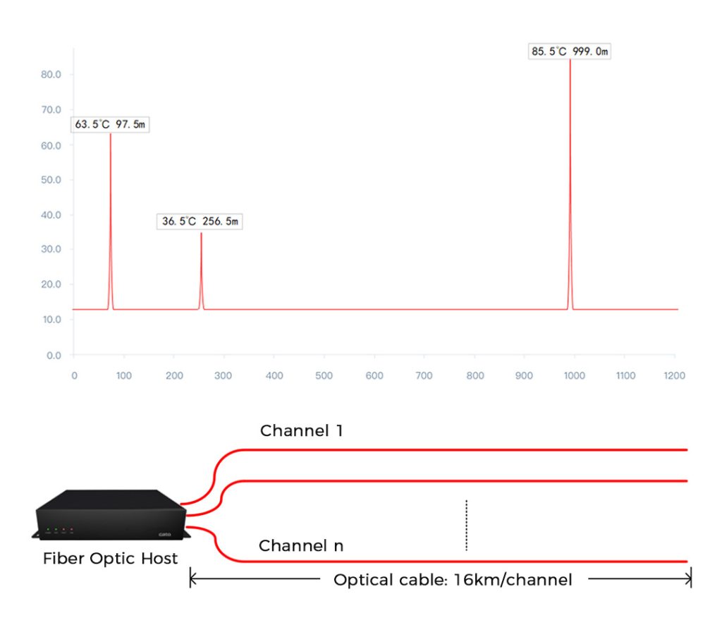
| DTS (Distributed Temperature Sensing) | Raman/Brillouin scattering analysis | Large-scale monitoring along entire transformer | ±1°C |
Fluorescence-based sensors dominate in transformer applications because they can be embedded directly within windings during manufacturing without electrical risk.
Key Applications in Power Transformers
Winding Hot-Spot Measurement
This is the most critical function of fiber optic sensors.
- Fibers are embedded during transformer coil winding.
- Sensors measure real-time hot-spot temperature, not estimated values.
- Data helps adjust load capacity and cooling dynamically.
Manufacturers like ABB, Siemens, and GE integrate 4–12 probes per transformer to capture temperature variations between phases and coils.
Oil and Core Temperature Monitoring
In oil-filled transformers, fibers are placed at different depths within the oil channels.
- Tracks oil stratification and cooling efficiency.
- Prevents overheating during overloading or pump failure.
- Enhances thermal model accuracy.
For dry-type transformers, FBG sensors attached to the core detect heat buildup during high current loading.
Thermal Modeling and Overload Control
FOTS data integrates with thermal models to optimize performance.
- Enables Dynamic Thermal Rating (DTR) for real-time load adjustment.
- Provides feedback to automatic cooling control (fans, pumps).
- Predicts thermal aging and remaining insulation life.
This ensures maximum utilization without exceeding thermal limits.
Integration with Transformer Monitoring Systems
Modern transformers are equipped with digital monitoring systems like SCADA, IoT-based platforms, or proprietary diagnostic units. Fiber optic sensors feed critical temperature data to these systems for centralized control and analytics.
Key Integration Features
- Real-time visualization of winding and oil temperature profiles.
- Automatic alarms for thermal thresholds.
- Predictive analytics combining FOTS + Dissolved Gas Analysis (DGA).
- Data sharing with utility management systems for remote diagnostics.
This integration transforms a transformer into a smart asset capable of predictive maintenance and failure prevention.
Installation and Maintenance Considerations
Installation
- Sensors are embedded during transformer manufacturing, often near high-current windings.
- Fibers are routed through sealed feedthroughs to prevent oil leakage.
- Interrogator units are installed outside the tank for data acquisition.
Maintenance
- Virtually maintenance-free due to immunity from oil contamination and electrical stress.
- No recalibration is required for over a decade.
- System verification involves optical signal validation rather than direct probe testing.
Installation challenges may occur in retrofitting older transformers, where integrating fibers into existing windings is difficult. Hence, most FOTS are implemented during new transformer production.
Challenges and Limitations
While fiber optic technology is highly reliable, a few practical challenges remain:
- Initial Cost: Higher installation cost compared to RTDs.
- Installation Complexity: Requires specialized integration during winding.
- Fragility: Optical fibers need careful handling during assembly.
- Data Management: High-resolution thermal data requires robust processing systems.
However, when viewed over a 20–25-year operational period, the return on investment (ROI) is significant due to reduced maintenance, fewer failures, and longer transformer lifespan.
Future Trends in Transformer Temperature Monitoring
Smart Transformer Evolution
Next-generation transformers are integrating fiber optic sensors with other digital technologies:
- Digital Twins: Real-time simulation of transformer behavior based on live temperature data.
- AI-Enhanced Predictive Maintenance: Algorithms analyze trends for early fault detection.
- Hybrid Sensing Systems: Combining optical temperature, pressure, and moisture sensing.
- Eco-friendly Designs: Use of biodegradable insulating oils monitored by optical sensors.
The shift toward smart substations and grid modernization will make fiber optic sensors a standard component in high-voltage equipment worldwide.
Fiber optic temperature sensors are transforming transformer monitoring. Their non-electrical design, precision, and durability outperform traditional sensors in high-voltage settings. Delivering real-time, accurate data from windings, they enhance reliability and extend lifespan. As smart grids advance, FOTS are becoming standard in next-generation transformers—offering safer, more efficient, and future-ready power solutions.