October 28, 2025

Fiber Optic Temperature Sensor in the Oil & Gas Industry
Blogs

Fiber Optic Temperature Sensor in the Oil & Gas Industry: From Downhole to Pipeline Monitoring

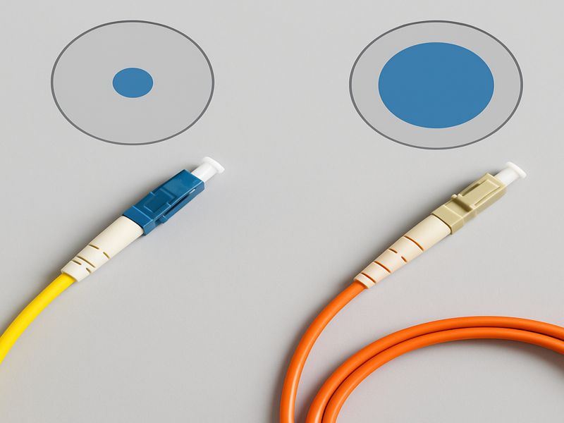
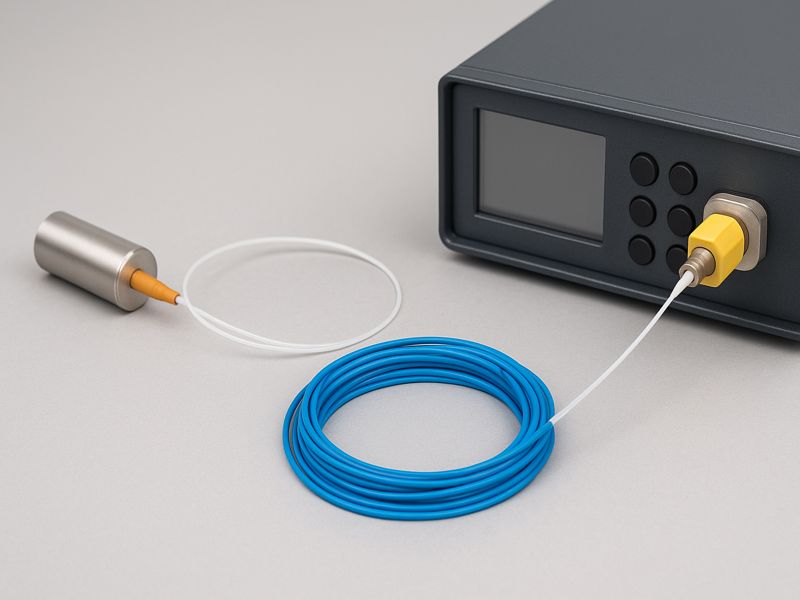
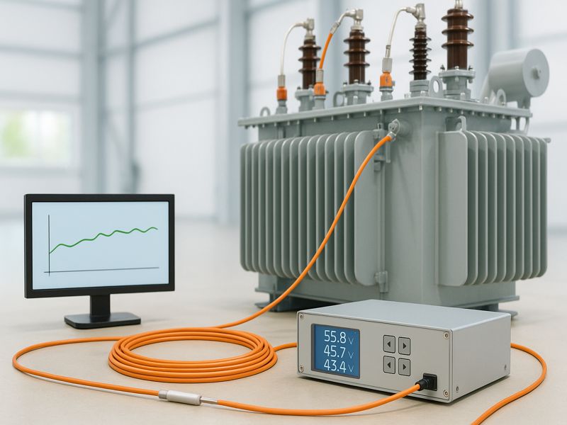
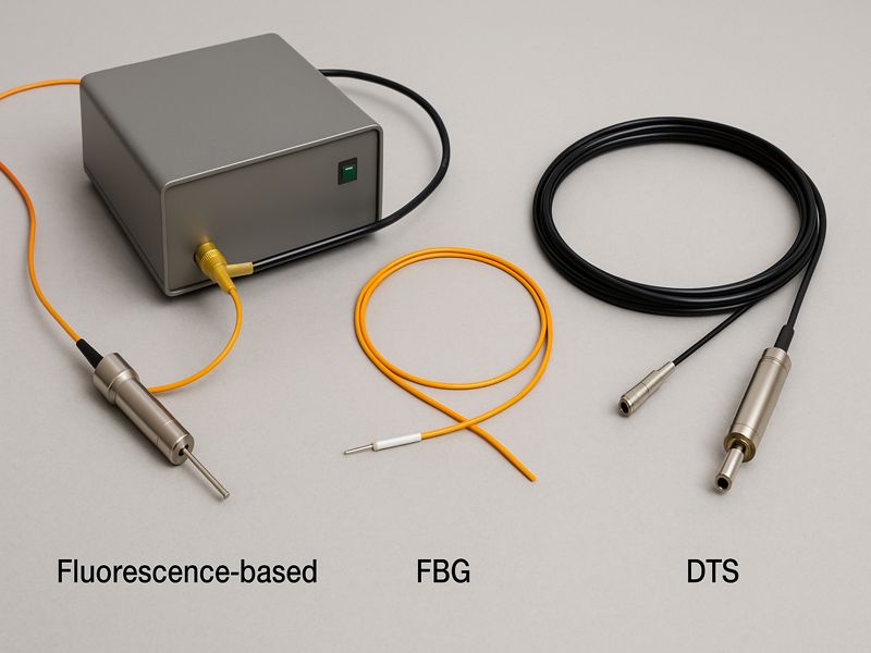
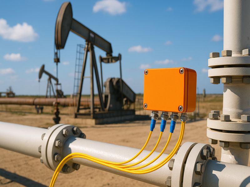
Temperature critically impacts safety, efficiency, and reliability in oil and gas operations. Conventional sensors like thermocouples and RTDs struggle under extreme heat, pressure, and EMI, prompting a shift toward fiber optic temperature sensors (FOTS). Using light instead of electricity, FOTS delivers real-time, interference-free, and long-distance monitoring across wells, pipelines, refineries, and storage sites—revolutionizing thermal management throughout the industry. The Need for Advanced Temperature Monitoring in Oil & Gas In oil and gas operations, temperature serves as an indicator of system integrity and performance. Deviations from expected temperature profiles can reveal early signs of equipment malfunction, leaks, or process inefficiencies. Challenges Faced by Traditional Sensors Harsh environments: Downhole wells and pipelines experience pressures exceeding 10,000 psi and temperatures above 200°C. Electromagnetic interference: Electrical sensors can produce inaccurate readings in the presence of strong EMI from motors or power lines. Accessibility: Physical inspection and replacement of sensors in deep wells or long pipelines are costly and time-consuming. Safety concerns: Electric-based systems pose ignition risks in explosive environments. In contrast, fiber optic systems overcome these challenges by offering distributed, passive, and intrinsically safe sensing over tens of kilometers — making them indispensable for modern oilfield monitoring. Principles of Fiber Optic Temperature Sensing Fiber optic temperature sensors rely on light propagation within optical fibers. When temperature changes, it affects the light’s properties — such as intensity, wavelength, or phase — enabling precise temperature detection. Important Technologies Fiber Bragg Grating (FBG) Sensors: Certain light wavelengths that change in response to strain or temperature are reflected by these sensors. They are suitable for point-based measurements with very high accuracy. Raman Scattering (Distributed Temperature Sensing, DTS): DTS systems analyze backscattered light caused by Raman scattering. Temperature data is continuously transmitted through the fiber by comparing anti-Stokes and Stokes scattering signal ratios. Brillouin Scattering Sensors: Used for both temperature and strain sensing, offering longer range (up to 100 km) and higher precision for pipeline and structural health monitoring. Comparison of Fiber Optic Temperature Sensing Technologies Technology Measurement Type Range Accuracy Key Applications Fiber Bragg Grating (FBG) Point-based Up to 10 km ±0.1°C Downhole, wellhead, tanks Raman DTS Distributed Up to 50 km ±1°C Pipelines, refineries Brillouin DTS Distributed (Temp & Strain) Up to 100 km ±0.5°C Long pipelines, structural monitoring Advantages of Fiber Optic Temperature Sensors in Oil & Gas The oil and gas sector requires monitoring systems that can endure high pressure, temperature, vibration, and chemical exposure while providing reliable data for automation and safety. Principal Benefits EMI Immunity: Fiber optics is not affected by electromagnetic interference since they use light rather than electrical signals. High Accuracy Over Long Distances: Capable of continuous monitoring over tens of kilometers with minimal signal loss. Intrinsic Safety: Non-electrical operation eliminates ignition risk in hazardous areas. Durability: Able to withstand high heat, pressure, and corrosion. Real-time Data: Enables continuous monitoring and early fault detection. Traditional vs. Fiber Optic Temperature Sensors Parameter Traditional (RTD/Thermocouple) Fiber Optic Sensor Signal Type Electrical Optical Range < 1 km Up to 100 km EMI Resistance Low High Accuracy ±1–2°C ±0.1–0.5°C Maintenance High Low Intrinsic Safety No Yes These advantages make fiber optic sensors ideal for upstream (drilling and production), midstream (transport), and downstream (refining and storage) operations. Downhole Temperature Monitoring Applications Downhole temperature monitoring plays a critical role in optimizing production, ensuring well integrity, and improving recovery efficiency. Typical Use Cases Steam Injection & Thermal Recovery: Monitoring the temperature profile along the wellbore during steam-assisted gravity drainage (SAGD) helps operators ensure even heat distribution. Hydraulic Fracturing: Real-time temperature mapping detects fluid movement, fracture propagation, and potential leaks. Zonal Isolation: Identifies leaks in packers and flow barriers that can compromise well performance. Pipeline Monitoring Applications Temperature variations along pipelines often indicate abnormal flow, leaks, or insulation failures. Fiber optic sensors provide continuous monitoring across entire pipeline lengths, enabling faster detection and response. Applications Leak Detection: Sudden drops in temperature indicate escaping fluids in liquid pipelines. Flow Monitoring: Detecting temperature gradients reveals flow distribution and potential blockages. Subsea Pipelines: Fiber optics withstands the extreme pressures and long distances of subsea environments. Pipeline Monitoring Methods Compared Monitoring Method Coverage Response Time Sensitivity Maintenance Cost Electrical Sensors Localized Slow Moderate High Acoustic Sensors Localized Fast Moderate High Fiber Optic DTS Continuous (Up to 100 km) Instant High Low Storage and Refining Applications Fiber optic temperature sensors also play a significant role in downstream operations, particularly in refineries, LNG plants, and large storage tanks. Applications Tank Temperature Profiling: Detects stratification and ensures uniform thermal conditions for stored hydrocarbons or LNG. Process Optimization: Real-time temperature tracking enhances control of distillation, cracking, and reforming processes. Safety Monitoring: Detects overheating, ensuring compliance with safety standards and preventing fire or explosion risks. In LNG terminals, fiber optic sensing can monitor both temperature and strain in cryogenic conditions, ensuring pipeline and tank integrity during repeated thermal cycles. Integration with SCADA and Digital Oilfield Systems The true power of fiber optic sensing is realized when integrated into modern Supervisory Control and Data Acquisition (SCADA) systems and digital oilfield architectures. Integration Benefits Real-Time Analytics: Enables operators to visualize continuous temperature profiles and automatically trigger alarms. Predictive Maintenance: Machine learning models can identify deviations from normal patterns, predicting failures before they occur. IoT Compatibility: Fiber sensors act as part of a connected ecosystem, feeding data to edge devices and cloud-based dashboards. For instance, integrating DTS data with acoustic (DAS) and pressure sensors in a unified SCADA dashboard allows for multi-parameter diagnostics, improving accuracy in fault localization and operational decision-making. Installation and Maintenance Considerations Although fiber optic systems offer superior performance, successful deployment requires careful design and execution. Installation Factors Cable Design: Must withstand mechanical stress, temperature extremes, and chemical corrosion. Connection Points: Proper termination and splicing ensure minimal signal loss. System Calibration: Regular calibration maintains accuracy over long-term operation. Maintenance and Cost Considerations Lower Long-Term Costs: Despite higher initial investment, FOTS reduces downtime and maintenance frequency. Data Management: High-resolution distributed data requires efficient data storage and analysis infrastructure. Reliability: With no moving parts and high durability, FOTS systems

Blogs

Comparing Single-Mode vs. Multi-Mode Fiber in Intrusion Detection Systems

FOIDS are transforming security by turning fiber cables into continuous sensors that detect vibrations, temperature shifts, and disturbances along fences, pipelines, or tunnels. Their performance depends on fiber type—Single-Mode (SMF) or Multi-Mode (MMF)—which differ in structure, range, dispersion, and cost. Choosing the right fiber impacts detection accuracy and reliability. This article compares SMF and MMF performance in intrusion detection applications. Fundamentals of Fiber Optic Sensing in Security Applications Fiber optic intrusion systems rely on the same principles that govern telecommunication networks, but instead of transferring data, they analyze light scattering patterns to sense physical changes. A part of the light is reflected back as Rayleigh backscatter when a coherent laser pulse passes through the fiber. Any external vibration, strain, or temperature change alters this signal, allowing distributed sensing technologies such as: Distributed Acoustic Sensing (DAS) – detects acoustic or seismic activity. Distributed Temperature Sensing (DTS) – identifies heat sources or fires. Distributed Strain and Temperature Sensing (DTSS) – measures both deformation and temperature. The fiber itself becomes the sensing medium — no external sensors are required. This enables long-range, continuous monitoring ideal for perimeter fences, tunnels, and buried pipelines. Single-Mode Fiber (SMF): Long-Range Precision Single-mode fiber has a small core diameter (≈9 µm) that allows only one propagation path (mode) for the light signal. By reducing modal dispersion, this design guarantees that the signal will stay coherent across extended distances. Key Characteristics Operating wavelength: 1310 nm and 1550 nm Attenuation: as low as 0.2 dB/km Transmission distance: up to 50–80 km without amplification Detection performance: highly stable, accurate over long runs Advantages Exceptional long-distance detection (tens of kilometers). Low signal noise and consistent backscatter profile. Excellent event localization accuracy (±1 m typical). High compatibility with distributed acoustic sensing (DAS) interrogators. Limitations Higher cost of transceivers and interrogators. Requires tighter splicing and alignment tolerances. Slightly less sensitive to small, localized disturbances due to narrow core size. SMF is the preferred choice for large-scale perimeter, border, and tunnel systems that demand both distance and precision. Multi-Mode Fiber (MMF): Short-Range Sensitivity Multi-Mode Fiber features a larger core diameter (50 µm or 62.5 µm) that allows multiple light propagation paths (modes). This structure increases backscatter intensity, making MMF inherently more sensitive to localized disturbances, but it also introduces modal dispersion — the spreading of signals over distance. Key Characteristics Operating wavelength: 850 nm or 1300 nm Attenuation: typically 0.5–1 dB/km Transmission distance: usually under 2 km for sensing Detection performance: higher local signal amplitude, lower range stability Advantages High local sensitivity due to a large core. Easier coupling and installation tolerances. Lower equipment and connector costs. Ideal for confined or short-distance facilities. Limitations Significant signal loss and dispersion beyond 2 km. Modal noise and unstable signal coherence at long range. Lower localization accuracy. MMF systems are well-suited for data centers, short fences, and indoor industrial sites, where detection distances are limited and cost sensitivity is high. Direct Comparison: Single-Mode vs. Multi-Mode Fiber Parameter Single-Mode Fiber (SMF) Multi-Mode Fiber (MMF) Core Diameter 8–10 µm 50–62.5 µm Propagation Modes One Multiple Typical Range Up to 50 km 0.5–2 km Backscatter Strength Lower but stable Higher but noisy Modal Noise Minimal Significant beyond 1 km Localization Accuracy ±1–2 m ±3–10 m System Cost Moderate to High Low to Moderate Installation Tolerance Precise alignment required Easier alignment Best For Long-range, high-security installations Short-range, cost-effective systems From a system design perspective, SMF offers superior range and accuracy, while MMF prioritizes cost and convenience. Performance in Specific Intrusion Detection Scenarios The right fiber choice depends on the operational context — distance, terrain, and threat profile. Application Scenario Recommended Fiber Type Key Considerations Long Perimeter Fences (e.g., airports, borders) Single-Mode Requires long-range detection and minimal false alarms Metro and Railway Tunnels Single-Mode Stability under vibration and temperature change Short Facility Perimeters Multi-Mode Economical for a < 1 km range Data Centers and Building Intrusion Multi-Mode Short run, easy integration with existing fiber Industrial Plants or Refineries Hybrid (SMF + MMF) Combines long coverage with localized sensitivity Hybrid deployments are increasingly common — using single-mode fiber for long-distance runs and multi-mode for zone-specific detection near entry points or machinery areas. Sensitivity and Signal Behavior Acoustic and Vibration Sensitivity Multi-Mode fiber generates stronger Rayleigh backscatter signals because of its larger core, enhancing local vibration sensitivity. Single-Mode fiber, although less intense locally, maintains consistent backscatter over long runs, ensuring uniform detection sensitivity. Localization Accuracy In distributed acoustic sensing, signal timing and coherence determine event localization. SMF’s single propagation path ensures predictable time delays, allowing precise localization (±1 m) even over 40 km. MMF’s multiple modes can distort timing and reduce accuracy beyond 1–2 km. Noise and False Alarms Multi-mode fibers are more prone to modal interference, leading to higher false alarm potential unless advanced filtering algorithms are applied. Single-mode fibers maintain a cleaner baseline, simplifying pattern reco System Cost and Maintenance Installation and Hardware Costs SMF systems use more sophisticated interrogators with narrow-band lasers and high dynamic range photodiodes, resulting in higher upfront costs. MMF systems employ cost-effective light sources (LED or VCSEL) and lower-precision connectors. Maintenance and Longevity Both fiber types require minimal maintenance once installed, but SMF offers longer service life in harsh outdoor conditions due to tighter jacket designs and lower signal degradation. Cost Category Single-Mode Fiber Multi-Mode Fiber Cable Cost (per km) Moderate Low Interrogator / Equipment High Low to Moderate Installation Complexity High (precision splicing) Low Maintenance Frequency Low Moderate Total Lifecycle Cost Higher upfront, lower long-term Lower upfront, higher long-term For organizations prioritizing long-term reliability and reduced false alarms, SMF systems often deliver better ROI despite higher initial costs. Environmental and Deployment Considerations Temperature and Humidity Both SMF and MMF operate effectively between –40 °C and +85 °C, but SMF demonstrates better performance stability under thermal expansion or humidity variation due to smaller core and consistent refractive index profile. Vibration and Mechanical Stress Tunnels, bridges, and buried routes expose fibers to vibration. SMF’s lower dispersion maintains accuracy under stress, while MMF can show fluctuating sensitivity with microbends

What Is a Fibre Optic Temperature Sensor
Blogs

What Is a Fibre Optic Temperature Sensor?

Temperature is critical to the safety and performance of systems in power, oil and gas, manufacturing, and transport. As operations grow harsher, traditional sensors like thermocouples and RTDs face limits from interference, range, and safety issues. Fiber optic temperature sensors overcome these challenges by using light instead of electricity, delivering accurate, interference-free, real-time temperature monitoring across long distances. This article examines their working principles, types, benefits, and applications. The Principle of Fibre Optic Sensing Fibre optic sensors operate on the principle that light traveling through an optical fiber can be influenced by external physical conditions—such as temperature, strain, or pressure. When temperature changes occur, they cause variations in the properties of the optical fiber (such as refractive index or length), which in turn modify the transmitted light signal. In essence, fibre optic sensing relies on detecting these light changes—whether in intensity, phase, polarization, or wavelength—and translating them into precise temperature readings. Because optical fibers are made of glass or plastic and transmit light instead of electricity, they are inherently immune to electromagnetic noise and are safe for use in high-voltage or explosive areas. There are two main sensing modes: Point sensing: Measures temperature at specific, discrete locations. Distributed sensing: Monitors temperature continuously along the entire length of a fiber—sometimes over tens of kilometers. Components of a Fibre Optic Temperature Sensor A typical fibre optic temperature sensing system consists of several key components: Component Function Optical Fiber Serves as the transmission path for light signals. It can be made from glass (silica) or polymer, depending on the environment. Sensing Element The section of the fiber or attached device that responds to temperature (e.g., Fibre Bragg Grating, Raman/Brillouin scattering region). Interrogator/Analyzer Converts the reflected or scattered light into readable temperature data using spectrometry or optical time-domain reflectometry (OTDR). Protective Sheath or Housing Shields the fiber from mechanical stress, chemical exposure, or high heat, ensuring reliable performance in harsh environments. Each component works together to ensure accuracy, stability, and resilience over time, even in environments where electrical sensors would fail. Working Principle The working principle of a fibre optic temperature sensor can vary depending on the technology used, but all share a fundamental concept: light changes its properties based on temperature variations. An Example of Fibre Bragg Grating (FBG) Periodic changes in the refractive index are imprinted along the fiber core of an FBG sensor. A particular wavelength, known as the Bragg wavelength, is reflected when broadband light travels through the fiber. As temperature changes, the grating spacing and refractive index shift, causing the reflected wavelength to change. By monitoring this wavelength shift, temperature can be precisely calculated. The relationship can be expressed as: Δλ = (∂λ/∂T) × ΔT Where Δλ is the wavelength shift and ΔT is the temperature change. Other techniques, such as Raman and Brillouin scattering, rely on detecting backscattered light variations, which correspond to temperature gradients along the fiber’s length. Types of Fibre Optic Temperature Sensors Type Sensing Principle Key Features Applications Fibre Bragg Grating (FBG) Wavelength shift due to temperature and strain changes High accuracy, multiplexing capability Power systems, aerospace, medical devices Raman Distributed Temperature Sensor (DTS) Measures intensity ratio of Stokes and anti-Stokes Raman scattering Long-distance distributed sensing Oil pipelines, tunnels, power cables Brillouin Scattering Sensor Frequency shift proportional to strain and temperature Measures both temperature and stress Structural health monitoring, long-distance sensing Interferometric Sensors Optical phase difference detection Extremely high sensitivity Laboratory or precision applications Each technology serves distinct needs: FBG sensors are ideal for localized precision monitoring, while Raman and Brillouin systems are perfect for long-distance distributed applications like pipeline or tunnel monitoring. Key Advantages Fibre optic temperature sensors provide several advantages over conventional electrical sensing technologies: Immunity to Electromagnetic Interference (EMI) Because they transmit light, fibre optic sensors are unaffected by electromagnetic or radio frequency noise—making them ideal near high-voltage lines or substations. High Accuracy and Stability They deliver temperature readings with precision down to fractions of a degree Celsius, maintaining accuracy even under vibration or chemical exposure. Long-Distance Measurement Distributed systems can monitor temperature profiles along several kilometers of fiber, reducing the need for multiple sensors. Safety in Hazardous Environments Since they use no electrical current, they are safe in explosive atmospheres or flammable chemical plants. Compact and Corrosion-Resistant Design Optical fibers are thin, lightweight, and resistant to corrosion, making them suitable for integration into confined or harsh spaces. Multiplexing Capability A single optical fiber can accommodate dozens or hundreds of sensing points, simplifying cabling and reducing costs. Common Applications Because of its versatility and dependability, fiber optic temperature sensors are extensively utilized in many different industries. Power and Energy Real-time monitoring of transformer winding temperatures. Cable hot-spot detection in underground and submarine power transmission systems. Preventive maintenance in renewable energy systems such as wind turbines. Oil & Gas Monitoring of well temperatures downhole. Finding leaks in storage tanks and pipelines. Real-time reservoir temperature profiling. Industrial and Manufacturing Process control in refineries, chemical reactors, and furnaces. Monitoring high-voltage motors and generators. Temperature mapping in composite material curing processes. Transportation Tunnel fire detection systems in metro and railway infrastructures. Aircraft structural monitoring. Automotive engine testing and battery temperature control. Data Centers and IT Infrastructure Rack-level temperature tracking for efficient cooling management. Fiber network thermal integrity monitoring. Healthcare and Research Temperature sensing in MRI environments where electrical sensors cannot operate. Biothermal mapping in medical devices or laboratory instruments. Comparison with Conventional Sensors Parameter Fibre Optic Sensor Thermocouple/RTD Signal Type Optical (light-based) Electrical (voltage/resistance) EMI Resistance Immune Susceptible Measurement Range Up to several kilometers Localized, short-range Accuracy High (±0.1°C possible) Moderate Safety Intrinsically safe, non-electrical Risk of spark or short circuit Maintenance Low Moderate to high Installation Cost Higher initial, lower long-term Lower initial, higher maintenance Multipoint Capability Excellent (via multiplexing) Limited The comparison clearly shows that fibre optic temperature sensors excel in environments requiring high precision, long-range monitoring, and electrical isolation. Installation and Maintenance Considerations Proper installation and maintenance are key to ensuring optimal sensor performance. Installation Best Practices Route fibers carefully to avoid

Fiber Optic Temperature Sensor Transformer
Blogs

What Is a Fiber Optic Temperature Sensor for a Transformer?

In the power industry, transformer reliability is vital for stable energy distribution. Constant electrical and thermal stress can cause insulation failure or aging if temperatures exceed safe limits. Accurate, continuous monitoring is essential, yet traditional RTDs and thermocouples struggle in high-voltage, oil-filled environments. Fiber optic temperature sensors solve this challenge by using light instead of electricity, offering safe, precise, real-time data even under extreme transformer conditions. The Role of Temperature Monitoring in Transformers Temperature is the most important factor affecting transformer performance and lifespan. Every 6–8°C rise above the design limit can halve the insulation life according to IEEE and IEC standards. Key Monitoring Zones Winding hot-spots: Most critical region, often the cause of insulation failure. Core and yoke: Affects magnetic losses and oil circulation. Oil temperature: Reflects overall thermal behavior and cooling efficiency. When these areas overheat, it leads to oil oxidation, insulation deterioration, and efficiency loss. Thus, maintaining optimal temperatures ensures transformer longevity, safety, and load efficiency. What Is a Fiber Optic Temperature Sensor? A fiber optic temperature sensor is a non-electrical device that measures temperature using light transmission through optical fibers. Instead of relying on electrical resistance or voltage changes, it measures the effect of temperature on light properties such as wavelength, intensity, or fluorescence decay. Main Components Optical Fiber: Carries light signals safely through high-voltage regions. Sensing Probes: Placed at strategic points like winding or oil channels. Signal Conditioner / Interrogator: Converts optical data into temperature readings. Display or Data System: Displays data or sends it to the transformer control unit. Because light is immune to electromagnetic interference and the fibers are non-conductive, fiber optic sensors are intrinsically safe for high-voltage transformer environments. Working Principle of Fiber Optic Temperature Sensors in Transformers Fiber optic sensors operate based on light interaction with temperature-sensitive materials. In transformer applications, two main technologies are used: Fluorescence-based Sensors (Fluoroptic®): These use a temperature-sensitive phosphorescent material at the fiber tip. When illuminated, it emits light that decays over time. The decay rate changes with temperature, allowing precise temperature measurement. Sensors for Fiber Bragg Grating (FBG): The fiber core of FBGs is engraved with tiny gratings. As temperature changes, the reflected wavelength (Bragg wavelength) shifts linearly, giving accurate temperature readings. Simplified Operation Flow Light is emitted from the interrogator into the fiber. The sensor probe at the target location reflects or re-emits light based on temperature. The temperature is ascertained by analyzing the signal that is returned. Results are transmitted to the transformer monitoring system in real-time. This method enables direct, multi-point measurement even inside energized windings—something impossible with electrical sensors. Advantages of Fiber Optic Temperature Sensors in Transformers Fiber optic sensors offer transformative benefits over traditional electrical sensors, particularly in oil-filled power transformers. Key Advantages Electrical Isolation: Non-conductive fibers eliminate short-circuit risks. Immunity to EMI: No interference from high magnetic fields or switching transients. Hot-Spot Accuracy: Direct measurement inside windings where heat originates. Safety: Fully safe in high-voltage oil-filled environments. Durability: Resistant to oil, pressure, vibration, and high voltage. Low Maintenance: No recalibration required over long lifespans. Fast Response: Instant detection of temperature rise during load surges. Fiber Optic vs. Conventional Temperature Sensors Feature RTD / Thermocouple Fiber Optic Temperature Sensor Signal Type Electrical Optical (Light-based) Electrical Conductivity Conductive Non-conductive EMI Sensitivity High None Measurement Location External / surface Directly in winding Accuracy ±2–3°C ±0.5°C or better Safety Risk of electric arc Intrinsically safe Response Time Slow Fast (milliseconds) Maintenance Frequent calibration Virtually maintenance-free Types of Fiber Optic Temperature Sensors Used in Transformers Different fiber optic sensing technologies serve different transformer applications, depending on accuracy, environment, and system size. Type Working Principle Application Accuracy Fluorescence-based Measures fluorescence decay Winding hot-spot measurement ±1°C FBG (Fiber Bragg Grating) Reflects wavelength shifts Core, bushing, external areas ±0.1°C DTS (Distributed Temperature Sensing) Raman/Brillouin scattering analysis Large-scale monitoring along entire transformer ±1°C Fluorescence-based sensors dominate in transformer applications because they can be embedded directly within windings during manufacturing without electrical risk. Key Applications in Power Transformers Winding Hot-Spot Measurement This is the most critical function of fiber optic sensors. Fibers are embedded during transformer coil winding. Sensors measure real-time hot-spot temperature, not estimated values. Data helps adjust load capacity and cooling dynamically. Manufacturers like ABB, Siemens, and GE integrate 4–12 probes per transformer to capture temperature variations between phases and coils. Oil and Core Temperature Monitoring In oil-filled transformers, fibers are placed at different depths within the oil channels. Tracks oil stratification and cooling efficiency. Prevents overheating during overloading or pump failure. Enhances thermal model accuracy. For dry-type transformers, FBG sensors attached to the core detect heat buildup during high current loading. Thermal Modeling and Overload Control FOTS data integrates with thermal models to optimize performance. Enables Dynamic Thermal Rating (DTR) for real-time load adjustment. Provides feedback to automatic cooling control (fans, pumps). Predicts thermal aging and remaining insulation life. This ensures maximum utilization without exceeding thermal limits. Integration with Transformer Monitoring Systems Modern transformers are equipped with digital monitoring systems like SCADA, IoT-based platforms, or proprietary diagnostic units. Fiber optic sensors feed critical temperature data to these systems for centralized control and analytics. Key Integration Features Real-time visualization of winding and oil temperature profiles. Automatic alarms for thermal thresholds. Predictive analytics combining FOTS + Dissolved Gas Analysis (DGA). Data sharing with utility management systems for remote diagnostics. This integration transforms a transformer into a smart asset capable of predictive maintenance and failure prevention. Installation and Maintenance Considerations Installation Sensors are embedded during transformer manufacturing, often near high-current windings. Fibers are routed through sealed feedthroughs to prevent oil leakage. Interrogator units are installed outside the tank for data acquisition. Maintenance Virtually maintenance-free due to immunity from oil contamination and electrical stress. No recalibration is required for over a decade. System verification involves optical signal validation rather than direct probe testing. Installation challenges may occur in retrofitting older transformers, where integrating fibers into existing windings is difficult. Hence, most FOTS are implemented during new transformer production. Challenges and Limitations While fiber optic technology is highly reliable, a

Installing FOIDS for Critical Infrastructure
Blogs

Top 10 Benefits of Installing FOIDS for Critical Infrastructure

Critical infrastructure—power grids, railways, pipelines, airports, and data centers—forms the backbone of modern economies and demands robust protection. Traditional systems like CCTV or motion sensors offer limited coverage, while FOIDS provide continuous, real-time monitoring using fiber cables as sensitive sensors. This article outlines the top 10 benefits of FOIDS, highlighting improved security, lower costs, and regulatory compliance. What Is FOIDS and How It Works FOIDS operates on the principle of distributed fiber optic sensing, where a laser pulse is transmitted along an optical fiber. As the light travels, small portions scatter back due to microscopic variations in the fiber’s structure—a phenomenon known as Rayleigh backscatter. Any disturbance—such as vibration, cutting, digging, or temperature change—alters the backscattered light pattern, which is analyzed by the interrogator unit to pinpoint the location and type of event. Core Technologies Behind FOIDS Distributed Acoustic Sensing (DAS): Detects vibration and acoustic disturbances such as footsteps, vehicles, or drilling. Distributed Temperature Sensing (DTS): Monitors heat buildup and fire events along cables or tunnels. Distributed Strain and Temperature Sensing (DTSS): Combines temperature and strain measurement for detecting ground movement or structural deformation. Unlike point sensors, FOIDS provides continuous coverage—every meter of fiber acts as a detection point. Benefit #1: Continuous Real-Time Monitoring Traditional systems monitor only predefined zones or points. FOIDS transforms the entire fiber length—often spanning tens of kilometers—into a continuous line of defense. Operators can receive instant alerts of intrusion, vibration, or temperature change in real time. This continuous data stream is invaluable for high-risk assets like oil pipelines, border fences, and metro tunnels, where a delay of even seconds can mean catastrophic damage or service interruption. Benefit #2: High Localization Accuracy FOIDS can locate intrusion or disturbance events with pinpoint precision—often within ±1–2 meters. This allows rapid and targeted deployment of patrols or drones to the exact site of the event, minimizing downtime and false investigations. In pipeline or substation applications, precise localization supports automated decision-making, such as isolating a segment or redirecting flow until the issue is resolved. Benefit #3: Multi-Threat Detection Capability A single FOIDS installation can detect multiple threats simultaneously: Vibration or acoustic disturbances: cutting, climbing, or digging. Temperature anomalies: fire, overheating cables, or equipment failure. Ground or structural deformation: landslides or tunnel movement. This versatility means operators can replace several traditional systems with one unified solution. DAS, DTS, and DTSS technologies together deliver comprehensive situational awareness across both security and operational dimensions. Benefit #4: Long-Range Coverage FOIDS can cover 20–50 km per interrogator channel, depending on the fiber type and system configuration. In contrast, most traditional systems require multiple sensors and power sources at short intervals. Technology Typical Range per Unit Coverage Type Power Requirement FOIDS (DAS/DTS) 20–50 km Continuous linear Centralized (none in the field) Microwave / Radar < 500 m Point/sector Distributed field power Vibration Coils / Sensors < 100 m Localized Distributed CCTV Systems Line-of-sight only Sector visual Local power + lighting Benefit #5: Minimal Maintenance and Long Lifecycle Optical fibers are passive components—they contain no electronic parts, need no field power, and are immune to electromagnetic interference. The interrogator unit, typically housed in a control center, performs all detection and analysis remotely. This means fewer field visits, minimal maintenance, and long service lifespans exceeding 25 years. The absence of outdoor electronics also eliminates corrosion and environmental degradation, making FOIDS ideal for harsh or remote conditions such as deserts, offshore platforms, and mountainous borders. Benefit #6: Integration with Existing Infrastructure FOIDS can be integrated seamlessly with modern SCADA, Video Management Systems (VMS), and Access Control Platforms. The system can automatically do the following when an event is detected: Turn on adjacent cameras for visual confirmation. Trigger lighting or alarms. Notify control rooms via existing network protocols (TCP/IP, SNMP, Modbus). This integration turns FOIDS into a central nervous system for infrastructure security, providing real-time insights through a single command interface. Benefit #7: Enhanced Situational Awareness through Analytics Modern FOIDS employ advanced AI and machine learning algorithms that continuously learn from their environment. They can distinguish between a genuine intrusion (e.g., human activity or vehicle vibration) and environmental noise (e.g., wind, rain, or animal movement). This pattern-based learning dramatically reduces false alarm rates—an essential factor for mission-critical environments where alarm fatigue can lead to delayed responses. FOIDS data can also be fed into predictive analytics platforms, providing early warnings of repetitive disturbances before they escalate into security breaches. Benefit #8: Cyber-Physical Security and Regulatory Compliance Governments worldwide are implementing stricter Critical Infrastructure Protection (CIP) regulations that require continuous monitoring and traceable event logging. FOIDS supports this compliance by offering: Encrypted communication channels. Role-Based Access Control (RBAC) for operator authentication. Audit trails and event logs that can be used for regulatory reporting or forensic analysis. By meeting these cybersecurity and physical protection requirements, FOIDS helps operators align with standards such as NERC CIP, EU CER Directive, and ISO/IEC 27001. Benefit #9: Cost Efficiency Over Long Distances While the initial investment in FOIDS equipment may be higher than in point sensors, the lifecycle cost is significantly lower. Reasons include: No distributed electronics or power along the fence or route. Lower maintenance frequency. Centralized monitoring for multiple zones via a single interrogator. Cost Factor Traditional Systems FOIDS Savings (Approx.) Field Hardware High (many units) Minimal (fiber only) 40–60% Power & Cabling Distributed power Centralized 30–50% Maintenance Frequent site visits Remote diagnostics 50–70% Service Life 8–10 years 20–25 years Longer lifespan Over the system’s lifetime, FOIDS often proves to be the most cost-effective solution per kilometer of protection. Benefit #10: Future-Proof Scalability FOIDS platforms are highly scalable. As infrastructure expands, operators can: Extend fiber coverage without replacing the entire system. Add new channels to interrogators for additional zones. Upgrade firmware to enhance detection algorithms. Because the sensing medium (fiber) is passive and future-compatible, FOIDS can integrate with emerging technologies like digital twins, smart infrastructure analytics, and AI-driven command centers. Real-World Applications and Case Studies Power and Energy A major power utility deployed FOIDS around 12 substations to prevent copper theft. After installation, theft

Fiber Optic Temperature Sensor
Blogs

How to Choose the Right Fiber Optic Temperature Sensor for Your Application

As industries push for greater efficiency and safety, demand for advanced sensing has surged. Fiber optic temperature sensors (FOTS) have emerged as a transformative solution, using light instead of electricity for precise, interference-free monitoring in harsh, high-voltage, or explosive environments. Choosing the right FOTS is essential—an incorrect match risks inaccurate readings or integration issues. Whether for power, oil, aerospace, or medical applications, proper selection ensures accuracy, reliability, and long-term performance. Understanding Fiber Optic Temperature Sensors Basic Working Principle A fiber optic temperature sensor measures temperature by detecting changes in light transmitted through an optical fiber. These changes occur due to variations in physical properties such as refractive index, fluorescence decay, or Bragg wavelength shifts. Because the signal is optical rather than electrical, the system is immune to EMI (Electromagnetic Interference) and suitable for electrically noisy or hazardous areas. Comparison with Traditional Sensors Unlike thermocouples or resistance temperature detectors (RTDs), fiber optic sensors: Provide long-distance sensing (up to tens of kilometers). Operate safely in high-voltage or explosive environments. Offer multi-point or distributed sensing capabilities. Require minimal maintenance and recalibration. Main Types of Fiber Optic Temperature Sensors Type Principle Temperature Range Accuracy Typical Application Fluorescence-based Measures the fluorescence decay time of the doped material −200 °C to +450 °C ±0.5 °C Aerospace, cryogenic, R&D FBG (Fiber Bragg Grating) Detects wavelength shift from Bragg reflection −40 °C to +300 °C ±0.2 °C Transformers, motors, medical DTS (Distributed Temperature Sensing) Uses Raman/Brillouin backscatter for continuous temperature mapping −40 °C to +600 °C ±1 °C per km Pipelines, tunnels, cables Each type excels in specific conditions. FBG sensors deliver high precision at localized points, while DTS offers real-time profiling across long distances — ideal for infrastructure and process industries. Key Selection Criteria Choosing the right fiber optic temperature sensor requires balancing multiple technical and environmental factors. Below are the most critical parameters to evaluate. Temperature Range and Sensitivity Different sensors handle different temperature extremes. Fluorescent-based sensors perform well at ultra-low or ultra-high temperatures, while FBGs are optimized for moderate industrial ranges. Always match the sensor’s operational limit with your process requirements to avoid signal drift or damage. Number of Measurement Points If you need a few discrete readings (e.g., transformer hotspots), an FBG sensor array is sufficient. However, if your goal is continuous monitoring along a 10 km pipeline, a DTS system is necessary. Understanding whether your application requires point, multi-point, or distributed sensing is a key decision factor. Installation Environment Temperature sensors are often deployed in demanding conditions: high vibration, strong electromagnetic fields, or exposure to chemicals. Choosing the right fiber coating — such as polyimide for high-temperature tolerance or stainless-steel armoring for mechanical protection — ensures longevity. Accuracy and Resolution Precision matters in industries like aerospace or semiconductor manufacturing, where even minor temperature variations can cause material expansion or electronic drift. High-quality FBG sensors can achieve sub-degree accuracy, while DTS provides broader but less fine-grained data. Response Time In dynamic environments (e.g., engine testing or turbine monitoring), response time is critical. FBG sensors typically offer millisecond response, ideal for capturing transient events, whereas DTS response time is slower due to signal averaging along the fiber length. Compatibility with Existing Systems Integration ease affects the total cost of ownership. Verify that the optical interrogator supports your desired sampling frequency, communication protocol (Ethernet, Modbus, etc.), and software interface for SCADA or predictive-maintenance systems. Sensor Type vs. Application Matrix The following matrix summarizes which sensor types fit common industrial uses. Application Recommended Sensor Type Why It Fits Power Transformers FBG Detects localized hot-spots, immune to EMI Oil Wells DTS Monitors distributed temperature over kilometers Aerospace Engines Fluorescence Ultra-fast response, compact form factor Medical Devices Mini FBG Biocompatible, precise at the small scale Power Cables & Tunnels DTS Continuous thermal mapping for fault detection Nuclear Facilities Radiation-hardened FBG Resists radiation and high heat By aligning sensor type with your environment, you can prevent over-engineering (and overspending) while ensuring reliability. Environmental and Operational Considerations The surrounding environment has a direct impact on sensor durability and performance. Fiber Coating Materials: Polyimide – Excellent for high-temperature (up to +400 °C). Acrylic – Flexible and cost-effective for general use. Metal-coated fibers – Provide superior mechanical and chemical resistance. Pressure & Radiation: In nuclear or deep-sea settings, sensors must endure pressure fluctuations and radiation exposure. Specialized fiber types such as radiation-hardened silica fibers are essential. Moisture & Chemical Protection: Chemical plants or subsea systems require hermetically sealed connectors and protective sheaths to prevent water ingress or corrosion. Connectivity to Monitoring Systems Hardware and software must work together seamlessly for modern sensor systems to function. Optical Interrogators The interrogator converts optical signals into digital temperature data. Selection factors include: Wavelength range and resolution Sampling rate (up to 1 kHz for fast systems) Channel capacity (number of sensors) Data Acquisition and Analytics Fiber optic systems are often tied into SCADA or predictive maintenance software. Real-time analytics can flag anomalies, enabling condition-based maintenance instead of reactive repair. Calibration and Accuracy Assurance Even optical sensors require periodic calibration to ensure stability. Some manufacturers offer automatic recalibration algorithms or reference FBGs embedded within the fiber network. Trade-offs between Cost and Performance Although fiber optic sensors are more expensive initially, they usually save downtime and maintenance costs. Configuration Initial Cost Accuracy Maintenance Typical Use Single FBG Low ±0.2 °C Minimal Laboratory, transformer monitoring Multi-FBG Array Medium ±0.3 °C Low Industrial automation DTS System High ±1 °C Very Low Pipelines, tunnels, power cables A cost-benefit analysis helps determine ROI. For instance, in a power plant, installing FBG sensors may prevent a transformer failure that could cost millions in repairs and downtime. Thus, long-term savings often outweigh initial investment. Certification and Reliability Standards To ensure compliance and interoperability, consider the following standards: IEC 61757 – Defines testing and calibration for fiber optic sensors. IEEE C57.148: Recommendations for transformer temperature monitoring. The ASTM E2847 standard pertains to distributed fiber optic sensing. MIL-STD-810 – Environmental testing for aerospace and defense sensors. Choosing certified products not only guarantees performance but also simplifies

Railway with Fiber Optic Detection Systems
Blogs

Railway and Metro Tunnel Safety with Fiber Optic Detection Systems

Railway and metro tunnels are vital transport links handling heavy traffic in confined spaces where safety failures can be catastrophic. Traditional monitoring—using discrete sensors or manual checks—offers limited coverage and slow response. Fiber optic detection now enables continuous, real-time monitoring, transforming cables into distributed sensors that detect vibration, strain, temperature, and movement with precision. This article explores how such systems enhance tunnel safety, their key applications, and future innovations in rail monitoring. Understanding Fiber Optic Detection Systems Fiber optic detection systems operate on the principle of light backscatter analysis. Microscopic flaws in the glass cause some of the light that a laser pulse passes through an optical fiber to be scattered back. Variations in backscattered signals reveal environmental changes along the fiber—such as vibration, temperature shifts, or strain. Three core sensing technologies are used in tunnel applications: Technology Function Common Use Case Distributed Acoustic Sensing (DAS) Detects vibrations and acoustic disturbances Intrusion, rail faults, rockfalls Distributed Temperature Sensing (DTS) Measures temperature along the fiber Fire and heat detection Distributed Strain and Temperature Sensing (DTSS) Tracks both strain and temperature Structural deformation monitoring These systems provide continuous coverage over kilometers with no electronic components inside the sensing zone—making them durable, EMI-resistant, and low-maintenance. In tunnels where conditions are harsh and access is limited, these features translate into exceptional reliability. Safety Challenges in Railway and Metro Tunnels Tunnel environments combine several risk factors that demand constant vigilance: Structural and geological instability: Ground movement, rock deformation, or subsidence may stress tunnel linings. Fire and overheating: Equipment failures or cable fires can spread rapidly in enclosed tunnels. Unauthorized access or intrusion: Human or vehicle entry through maintenance shafts or portals can endanger operations. Track and rolling stock failures: Rail cracks, wheel impacts, or dragging components pose accident risks. Environmental hazards: Flooding, gas leakage, or electrical faults in confined spaces are hard to detect early. Given these challenges, traditional point-based sensors are inadequate. Fiber optic systems overcome this by offering distributed, real-time monitoring, transforming every meter of fiber into a safety sensor. How Fiber Optic Detection Enhances Tunnel Safety Continuous and Distributed Monitoring Unlike discrete sensors, fiber optic systems provide complete linear coverage. Every meter of the optical fiber acts as a detection node, ensuring no blind spots from portal to portal. Real-Time Event Localization The system can pinpoint the exact position of a vibration, heat source, or strain change—often within ±1–2 meters. This precision accelerates response and minimizes downtime. Multi-Hazard Detection One fiber can simultaneously detect vibration, temperature, and strain, offering multi-threat awareness (fire, intrusion, structural damage, or rail issues). Seamless SCADA Integration Fiber systems interface directly with tunnel SCADA (Supervisory Control and Data Acquisition) and VMS (Video Management Systems). When a heat or vibration anomaly is detected, the control center can automatically trigger ventilation, cameras, or alarms. Key Applications in Tunnel Safety Fiber optic detection systems are adaptable across multiple hazard categories: Application Area Primary Fiber Type Typical Benefits Fire & Heat Detection DTS Early warning of temperature rise and fire spread Structural Health Monitoring DTSS Detect lining strain, cracks, and settlement Intrusion Detection DAS Detect unauthorized entry or vandalism Track Fault Detection DAS Identify broken rails, dragging gear, or wheel impacts Rockfall / Ground Movement DAS / DTSS Detect seismic vibrations or tunnel roof instability These applications are particularly critical for long tunnels, underground metro lines, and mountainous railway corridors where physical inspection is impractical. System Architecture and Deployment Considerations A well-engineered deployment plan ensures reliability and precision. Fiber Placement: Cables are installed along tunnel walls, under tracks, or within cable trays. Buried configurations offer better vibration coupling for DAS, while wall-mounted routes are ideal for DTS fire detection. Installation Methods: Depending on the environment, fibers can be embedded, clamped, or run through protective ducts to ensure long-term durability. Signal Processing: The interrogator unit (DAS/DTS device) captures backscatter data and applies AI-based classification algorithms to filter noise and identify meaningful events. Localization and Calibration: Mapping fiber distance to tunnel coordinates is critical for accurate event positioning. Reference markers and calibration runs help maintain precision. Maintenance: Systems require minimal upkeep but should be periodically checked for optical loss, mechanical damage, and calibration drift. Case Studies and Real-World Implementations Case 1: Metro Tunnel Fire Detection in Europe A large metropolitan subway network implemented a Distributed Temperature Sensing (DTS) system along a 5-kilometer twin-tube tunnel. The system detected overheating in a cable tray before smoke appeared, enabling ventilation activation within 20 seconds and preventing service disruption. Result: 85% reduction in fire response time compared to traditional smoke sensors. Case 2: Mountain Railway Rockfall Monitoring in Asia A high-speed rail tunnel under mountainous terrain adopted DAS-based rockfall detection. The system identified impact vibrations near the tunnel entrance during heavy rainfall, automatically signaling maintenance crews. Result: Early alerts prevented potential derailment, saving millions in equipment repair costs. Case 3: Combined Safety and Structural Health in Metro Lines An urban rail operator combined DTS (for fire) and DTSS (for strain) along newly built tunnels. Data integration with the central SCADA system allowed unified monitoring dashboards for both safety and maintenance. Challenges and Limitations Challenge Description Mitigation Strategy Calibration Complexity Tunnel acoustics and material composition vary Use environment-specific AI models and adaptive calibration False Alarms Noise from passing trains or maintenance Implement pattern recognition and event validation logic Retrofitting Costs Integrating sensing fiber into existing tunnels can be costly Utilize spare or dark fibers in communication cables Data Management High-frequency data streams require robust storage Deploy edge processing and compressive analytics Environmental Harshness High humidity and vibration stress fiber hardware Use ruggedized, armored fiber cables and sealed enclosures Despite these limitations, operational benefits often outweigh initial installation challenges. Future Trends in Tunnel Fiber Optic Monitoring Artificial Intelligence and Machine Learning Next-generation systems use AI/ML models to classify acoustic or vibration patterns, distinguishing between a human intruder, equipment noise, or natural seismic events. This drastically lowers false alarm rates. Multi-Sensor Fusion Manufacturers are integrating DAS + DTS + DTSS into hybrid systems for simultaneous detection of vibration, temperature, and

Leave Your Message