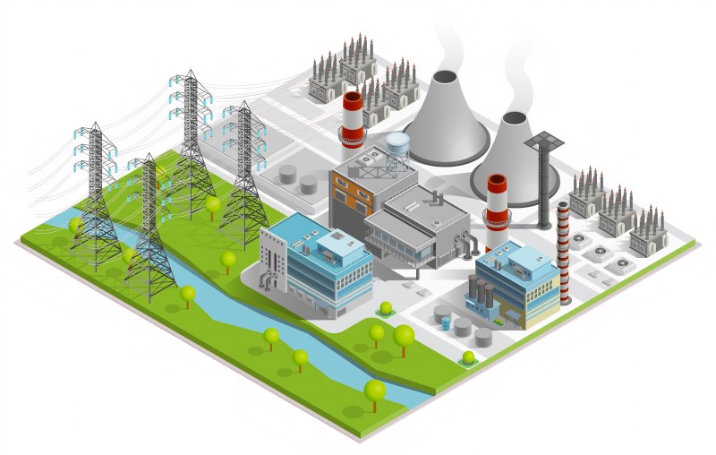
Power plants—thermal, nuclear, hydro, or renewable—operate under extreme stress, with maintenance consuming up to 40% of costs. Overheating in generators, transformers, and turbines causes failures and costly downtime. Traditional thermocouples and RTDs struggle in high-voltage environments, while fiber optic temperature sensors provide precise, real-time, interference-free monitoring—enabling predictive maintenance and lowering long-term costs.
Traditional Temperature Monitoring’s Drawbacks
The industry has long relied on conventional sensors like thermocouples and RTDs (Resistance Temperature Detectors), but these devices have built-in drawbacks that raise maintenance costs.
- Electrical Interference: Both RTDs and thermocouples use electrical signals that can be distorted by electromagnetic interference (EMI), especially in generator or transformer environments.
- Limited Coverage: They provide data only from specific points, making it difficult to detect localized hot spots deep within windings or cores.
- Frequent Calibration: These sensors drift over time, requiring regular recalibration and replacement.
- Safety Concerns: In oil-filled or high-voltage equipment, installing electrical sensors increases risk.
| Parameter | RTD | Thermocouple | Fiber Optic Sensor |
| Accuracy | ±1°C | ±2°C | ±0.1°C |
| Electrical Interference | High | Medium | None |
| Maintenance | Frequent | Moderate | Minimal |
| Service Life | 3 years | 5 years | 10+ years |
| Installation Safety | Moderate | Low | High |
How Fiber Optic Temperature Sensors Work
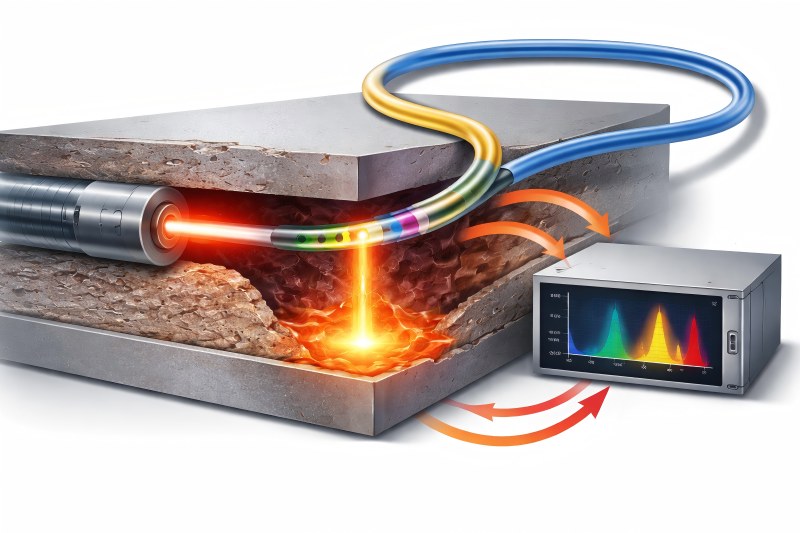
Fiber optic sensors measure temperature using light, not electricity. The principle involves transmitting light through optical fibers and analyzing the changes in reflected or scattered light that occur with temperature variations.
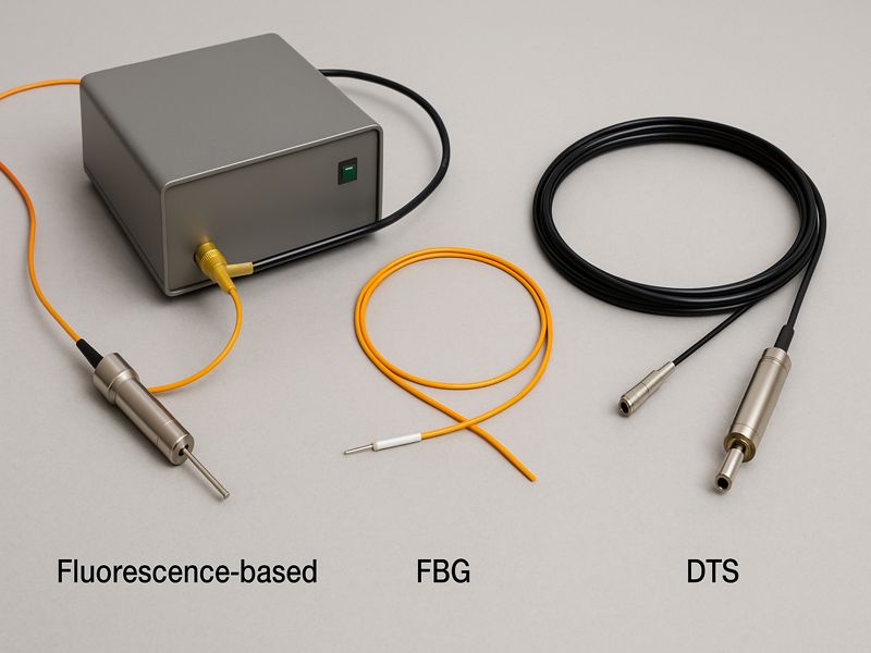
Three common technologies dominate the market:
- Fiber Bragg Grating (FBG): Measures wavelength shifts caused by temperature changes at specific grating points along the fiber.
- Raman-Based Distributed Temperature Sensing (DTS): Measures scattered light continuously along the entire fiber length, ideal for long-distance monitoring.
- Brillouin Sensing: Offers combined strain and temperature measurement for high-precision applications.
Because these systems are immune to EMI, nonconductive, and corrosion-resistant, they can safely operate inside generator windings, transformer oil, and turbine bearings—environments where electrical sensors would fail.
| Feature | RTD | Thermocouple | FBG Fiber Sensor | DTS System |
| Measurement Points | Single | Single | Multiple (up to 50+) | Continuous |
| Cable Length | <100 m | <100 m | >10 km | >30 km |
| EMI Immunity | Poor | Moderate | Excellent | Excellent |
| Response Time | Slow | Fast | Fast | Moderate |
| Typical Application | Panels | Pipes | Windings, Busbars | Transformers, Cables |
Applications of Fiber Optic Sensors in Power Plants
Generators
Fiber sensors embedded in stator windings offer real-time monitoring of internal temperatures. Unlike RTDs that can only measure outer layers, FOTS detect thermal gradients inside the winding pack.
Transformers
Fiber sensors monitor hotspots in windings and oil ducts, improving thermal management. Accurate data enables better load balancing and longer insulation life.
Turbines
Sensors placed in bearings, exhaust ducts, and stator frames detect overheating before it causes catastrophic mechanical failure.
Switchgear and Busbars
Continuous monitoring reduces fire risk and extends the lifespan of copper conductors by detecting abnormal temperature rise early.
| Equipment | Monitoring Location | Benefit of FOTS |
| Generator | Stator winding | Prevent winding burnout |
| Transformer | Oil channel & winding | Detect insulation hotspots |
| Turbine | Bearing & exhaust | Predict bearing wear |
| Switchgear | Busbar joints | Prevent arc flash failures |
Maintenance Cost Reduction Mechanisms
The real financial value of fiber optic temperature sensors lies in preventive and predictive maintenance. These systems deliver continuous, high-resolution thermal data that allows operators to act before failures occur.
a. Predictive Maintenance
By trending temperature patterns, operators can forecast failures weeks in advance and schedule maintenance at optimal times.
b. Reduced Downtime
Instead of relying on periodic inspections, maintenance is driven by real-time data. This reduces forced outages and boosts availability.
c. Longer Equipment Life
Consistent temperature control prevents material degradation, extending the lifespan of copper windings, insulation, and bearings.
d. Lower Labor and Calibration Costs
Optical sensors require virtually no recalibration, minimizing technician hours and spare parts inventory.
| Equipment | Conventional Annual Maintenance Cost | With FOTS | Cost Reduction (%) |
| Generator | US $50,000 | US $32,000 | 36% |
| Transformer | US $45,000 | US $28,000 | 38% |
| Turbine | US $60,000 | US $39,000 | 35% |
Integration and Retrofit Strategies
One of the advantages of fiber optic systems is their flexibility in installation—suitable for both new builds and retrofits.
New Installations
Manufacturers can embed FBG sensors directly into generator or transformer windings during assembly, offering permanent monitoring throughout equipment life.
Retrofits
For older assets, external clamp-on or insertion-based sensors can be installed without dismantling the equipment, integrating seamlessly with existing control systems (SCADA/DCS).
Data Integration
Modern FOTS solutions are compatible with predictive analytics platforms and IIoT dashboards, enabling real-time alerts and historical trend analysis.
| Integration Mode | Use Case | Complexity | ROI Period |
| Embedded FBG | New generator | Medium | 2–3 years |
| Clamp-on DTS | Existing transformer | Low | <2 years |
| Full IIoT Integration | Plant-wide upgrade | High | 3–4 years |
Case Studies and Real-World Results
Case 1: Hydropower Plant, Norway
- Challenge: Generator overheating led to repeated forced outages.
- Solution: Embedded FBG sensors for stator temperature mapping.
- Result: 50% reduction in failure incidents, saving $120,000 annually.
Case 2: Combined-Cycle Plant, UAE
- Challenge: Inconsistent bearing temperature readings during peak operation.
- Solution: Fiber optic sensors installed in turbine bearings and housings.
- Result: Improved data accuracy, 20% less downtime.
Case 3: Wind Farm, Spain
- Challenge: Frequent maintenance visits to remote turbines.
- Solution: Fiber optic temperature monitoring with remote diagnostics.
- Result: Maintenance visits cut by 40%, annual savings of €90,000.
Future Trends and Digital Integration
As the power industry embraces digital transformation, fiber optic temperature sensing is becoming central to data-driven maintenance ecosystems.
- Integration with AI: Automatic failure prediction and heat pattern analysis are possible with machine learning methods.
- Digital Twins: Combining FOTS data with virtual models allows simulation of equipment performance under different load scenarios.
- IIoT Platforms: Cloud-based analytics enable centralized monitoring of multiple sites.
- Green Energy Alignment: FOTS helps optimize renewable assets by ensuring efficient temperature control in inverters, storage systems, and high-voltage equipment.
Economic and Environmental Benefits
The advantages of FOTS extend beyond maintenance savings—they also deliver sustainability and energy-efficiency gains.
Financial Gains
- Up to a 40% decrease in upkeep expenses.
- Increased operational availability and reliability.
- Lower insurance premiums due to reduced failure risk.
Environmental Benefits
- Reduced material waste from fewer sensor replacements.
- Optimized energy efficiency through thermal balancing.
- Contribution to carbon-reduction targets by minimizing downtime and energy loss.
| Benefit Type | Metric | Improvement with FOTS |
| Maintenance Cost | Annual O&M | ↓ 30–40% |
| Downtime | Unplanned outages | ↓ 25–35% |
| Energy Efficiency | Thermal management | ↑ 10–15% |
| Environmental Impact | Equipment waste | ↓ 20% |
Fiber optic temperature sensors are reshaping how power plants manage maintenance and reliability. By providing real-time, interference-free, and distributed temperature data, they enable operators to transition from reactive maintenance to predictive asset management.
The result is clear: lower maintenance costs, improved safety, longer equipment life, and enhanced sustainability. As utilities worldwide pursue digital transformation and decarbonization goals, adopting fiber optic sensing is not merely a technical upgrade—it’s a strategic investment in the future of efficient and resilient power generation.