Laser Beam Detector Alignment and Debugging Guide: How to Set Up a Stable Perimeter Security System
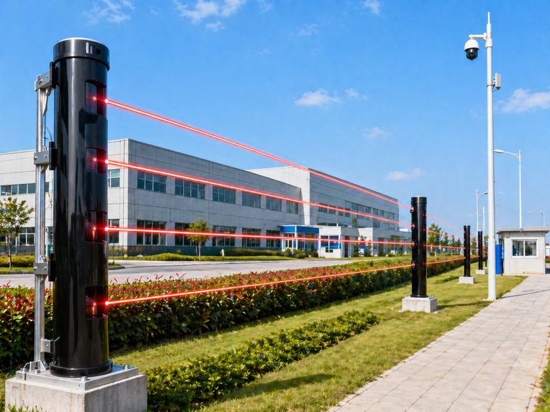
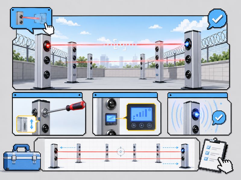
Laser beam detectors protect factories, substations, warehouses, airports, solar farms, and other outdoor sites by sending an alarm when beams are blocked. Common commissioning issues, such as unstable signals or false alarms, usually come from poor alignment, weak fixing, wrong settings, cable problems, or incomplete testing. This guide covers beam alignment, signal strength, alarm settings, false alarm causes, system testing, and final inspection. What Signal Strength Is Considered Qualified? Signal strength is one of the most important indicators during laser beam detector alignment. If the receiver cannot receive a stable beam signal, the detector may trigger false alarms or fail to detect real intrusions. In many installations, the basic recommendation is that the receiver signal strength should not be lower than 50%. This level can usually support normal operation under basic conditions. However, for real outdoor perimeter security projects, a higher standard is recommended. For better stability, it is safer to adjust the signal strength to 70% or above. A stronger and more stable signal provides better resistance against wind, vibration, dust, light interference, and slight installation movement. This is especially important for outdoor fences, long-distance beam protection, substations, industrial sites, and areas with changing weather. Signal Strength Installation Meaning Recommendation Below 50% Weak signal, high risk of missed alarms or false alarms Re-align immediately Around 50% Basic qualified level Acceptable for short-distance indoor use 70% or above More stable signal reception Recommended for outdoor projects Very high but unstable Possible reflection or off-center receiving Check angle and surrounding objects When aligning the beam, test the signal several times from different positions. Do not rely on one quick reading. The best result is not only a high value, but also a stable value. Correct Way to Start Alignment Mode Before adjusting the beam direction, the transmitter and receiver should enter the correct debugging mode. Many installation problems happen because the device is not in the right setting mode. On the transmitter side, use the mode switch button to enter alignment mode. Usually, the installer needs to press and hold the mode switch button for several seconds until the device enters the correct mode. After entering alignment mode, the visible laser helps the installer make a rough visual alignment. This visible beam is useful for the first adjustment. It allows the installer to confirm whether the transmitter is generally pointing toward the receiver. However, visual alignment is only the first step. Final adjustment must still depend on the receiver signal strength display. On the receiver side, enter the settings menu and switch to the signal strength display interface. In many devices, this is done by pressing the setting button for several seconds, then using the function switch button to select the correct menu. Once the receiver displays signal strength, the installer can adjust the transmitter until the signal becomes stable. How to Adjust the Transmitter Beam Position After entering alignment mode, the next step is to adjust the transmitter beam position. The transmitter usually has beam adjustment holes or internal adjustment screws. The beam direction can be easily adjusted using a Phillips screwdriver. The beam should be adjusted in two directions: Horizontal direction, also called the X-axis adjustment Vertical direction, also called the Y-axis adjustment The goal is to make each laser beam accurately reach the receiver’s sensing area. For multi-beam laser detectors, each beam should be adjusted one by one. After one beam is completed, switch to the next beam and continue adjustment until all beams are properly aligned. During adjustment, do not move too quickly. Small changes in the screw position may cause large changes in the beam angle, especially for long-distance installations. Adjust slowly, observe the receiver signal, and stop when the signal reaches a stable high level. Adjustment Step Operation Key Point Step 1 Enter transmitter alignment mode Use a visible laser for rough aiming Step 2 Adjust X-axis Move the beam left or right Step 3 Adjust Y-axis Move beam up or down Step 4 Check the receiver display Confirm stable signal strength Step 5 Switch to the next beam Repeat until all beams are aligned For outdoor projects, installers should also check whether the transmitter and receiver are firmly mounted. If the pole, bracket, or base is loose, the signal may change after wind or vibration. Receiver Settings: How to Read Signal Strength The receiver is the key device for confirming alignment quality. Even if the beam looks visually correct, the receiver display should be used as the final reference. After entering the setting interface, switch to the signal strength page. The receiver should show the current beam mode, light level, or signal percentage. During alignment, observe whether the value rises or drops while adjusting the transmitter. A good alignment result should meet three conditions: The signal strength is high enough. The signal value is stable. The alarm status does not flash randomly. If the receiver display changes sharply, the beam may not be centered correctly. It may also be affected by reflection, unstable mounting, blocked lens, or incorrect beam height. After adjustment, exit the setting mode and return the device to working mode. Some laser beam systems allow the transmitter and receiver to switch automatically after debugging. In this case, the installer does not need to manually change the receiver mode again. Important Parameter Settings for Stable Operation Correct parameter settings are just as important as physical alignment. Even if the laser beam is aligned correctly, wrong parameters can still cause false alarms or missed alarms. 1. Beam Blocking Logic Many laser beam detectors support multi-beam alarm logic. The default setting may require two adjacent beams to be blocked at the same time before triggering an alarm. This helps reduce false alarms caused by insects, falling leaves, birds, or small objects. The beam blocking logic for high-security places should be chosen based on the degree of risk. If the system is too sensitive, false alarms may increase. If it is too loose, small intrusions may be missed. 2. Trigger Time Trigger time means how