


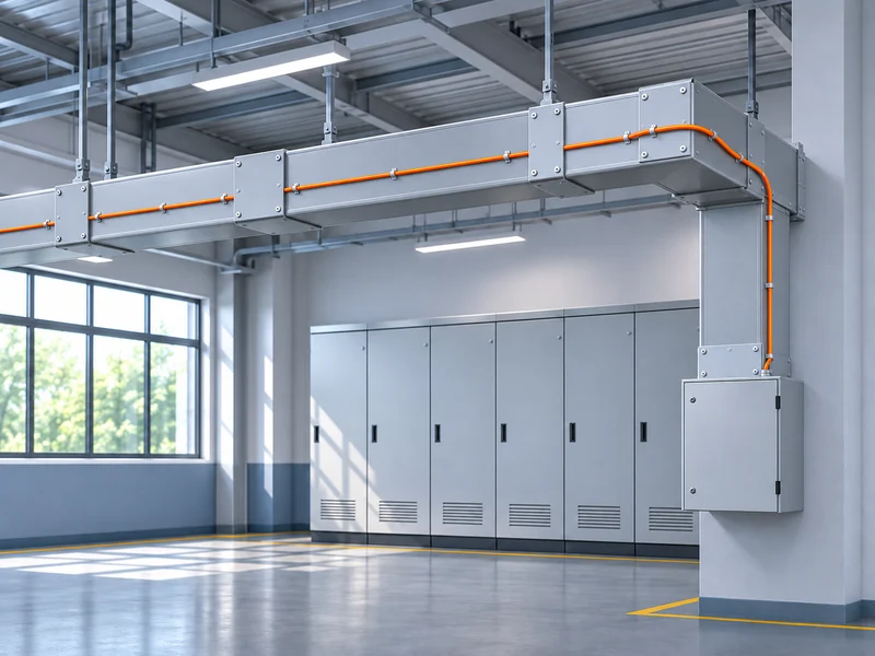
A busway temperature monitoring system should follow the electrical distribution layout and make abnormal heat identifiable at the relevant section. Begin with the busway topology, agree which thermal conditions need monitoring, and review where sensing fiber can be installed. Then connect temperature locations to section names and operating responsibilities.
Fiber optic DTS offers continuous measurement along an installed sensing path. For busways, its value depends on how that path relates to the equipment. Monitoring a convenient external route is useful only when the project understands what those readings represent.
Map the Busway Before Selecting the Sensing Route
Obtain the current busway layout, including straight sections, changes in direction, connections and branches. Identify the equipment supplied by each route where that information is available. This gives the monitoring design a physical and operational reference.
Check the drawing against accessible equipment. Extensions or replaced sections may not appear in an older plan. Resolve differences before assigning monitoring labels, because later corrections can affect both the route and alarm interpretation.
Record maintenance access as part of the survey. A sensing cable should not create unnecessary difficulty when a busway section or associated equipment needs inspection. Any routing detail around removable parts requires review by the equipment owner.
The survey should also identify the path back to the DTS host. Lead-in sections and stored cable affect the installation without necessarily representing additional busway coverage.
Separate Route Monitoring from Component Monitoring
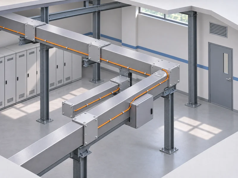
Define whether the objective is to observe temperature behavior along the busway enclosure, selected connection areas or other approved locations. Each objective requires a suitable sensing arrangement. Keep that distinction in the scope given to suppliers.
A continuous route can provide context around a localized change. However, a nearby fiber does not automatically measure an internal conductor or concealed connection. The design must explain the relationship between the thermal source and the accessible sensing location.
Identify any critical location that cannot be represented adequately by the proposed route. Evaluate that specific area separately rather than assuming the overall temperature profile will address the issue. A combination of monitoring methods may be appropriate where the requirements differ.
Gato’s comparison of point and distributed fiber optic temperature sensors explains the distinction between monitoring selected positions and following a continuous route. Use that distinction to define the busway requirement before choosing the equipment.
Select a Configuration for the Actual Monitoring Task
Gato identifies busways among the localized equipment applications for its E3 distributed temperature sensing system. Its product page describes a centimeter-level configuration for this type of monitoring.
Configuration selection should start with route length, the thermal regions that matter and the proposed installation. Ask how the chosen system will represent the busway sections and how its measurement behavior will be verified.
Avoid treating the product category as proof of suitability for every busway design. Enclosure construction, access and the mounting arrangement still require review. Confirm the sensing cable specification and the supported interfaces for the equipment being supplied.
The enquiry should also explain how operators will use the information. A local maintenance display and a centrally managed alarm workflow can impose different integration and documentation requirements.
Build a Coverage Matrix for Sections and Branches
Use the busway drawing to prepare a coverage matrix. Each row should represent a recognizable equipment section or a location requiring a separate monitoring decision. This makes omissions easier to see before installation.
The matrix should distinguish monitored routes from connecting fiber. It should also show where the proposed arrangement requires further approval or an additional monitoring method.
|
Busway element |
Design question |
Record to prepare |
|
Main straight section |
Which thermal condition will the route represent |
Approved sensing path |
|
Connection area |
Can the relevant heating reach the sensing cable |
Reviewed mounting detail |
|
Branch route |
How will its position be distinguished from the main run |
Branch identifier and route map |
|
Tap-off equipment |
What can be observed without obstructing access |
Scope and access review |
|
Vertical transition |
How will cable support and location mapping be maintained |
Transition detail |
|
Host connection |
Which cable portion serves only as a connection |
Lead-in and channel schedule |
Check the matrix against the monitoring objective. A fully populated drawing can still contain a location where the proposed temperature measurement does not answer the maintenance question.
Review Mounting and Thermal Contact
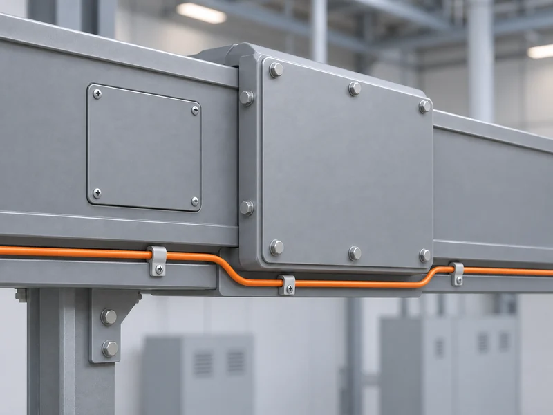
Select mounting details with the busway manufacturer and sensing supplier. The arrangement should preserve equipment access and respect the cable’s mechanical requirements. Avoid unapproved modifications to busway enclosures.
Clarify whether the fiber observes a surface or surrounding air. The same physical section can produce different measurements depending on that placement. The acceptance record should describe the arrangement precisely enough for maintenance staff to recognize changes later.
Consider how the mounting will be inspected and restored after work. A detail that is difficult to reproduce can introduce uncertainty after a section is opened or replaced. Photographs and approved drawings help preserve the intended arrangement.
Do not assign a universal cable spacing or attachment method from an unrelated installation. Use the detail approved for the selected equipment and verify the response it is intended to provide.
Connect Optical Distance to Equipment Identity
A branch in the electrical layout does not automatically become a matching branch in the optical sensing path. Show how the fiber actually travels through the installation and how each channel connects. This prevents the software map from implying a layout that the cable does not follow.
Prepare the location mapping after the final route is established. Include reserve loops, lead-ins and transitions so their optical distance is accounted for. Use familiar busway identifiers to mark positions, making them easy for operators and maintenance personnel to recognize.
During commissioning, check recognizable points along the route. Confirm that an event assigned to a branch or connection appears under the correct equipment label. An accurate distance value is insufficient if the operator follows it to the wrong section.
Keep the route map with the configuration record. Future extensions should update both together.
Define Alarm Zones Around Maintenance Decisions
Choose alarm zones that correspond to useful operating boundaries. A zone should help staff identify the affected equipment and decide who needs to respond. Avoid dividing the route only because equal sections are easy to draw.
Different monitored locations may have different normal thermal behavior. Review representative observations and available operating context before selecting alarm settings. Preserve the reasoning for those settings so later changes can be evaluated.
The alarm plan should identify:
- The busway section or branch represented by each zone.
- The thermal condition the installed sensing route measures.
- The warning information shown to the operator.
- The responsible maintenance team and escalation route.
- The response to unavailable or faulty measurements.
- The records needed after inspection or corrective work.
Keep operating warnings and system faults distinguishable. A lost measurement should not be interpreted as evidence that the busway has returned to a normal condition.
Make Integration Requirements Specific
Describe the information that must reach the receiving platform. This may include the equipment identity, reported location, temperature information and alarm state, according to the delivered system’s supported interface.
Agree how labels and units will appear across systems. A correctly transmitted value can still be misunderstood if its unit or asset association is missing. Check that the receiving display provides enough context for an operator to act.
Ask the supplier to clarify the specific communication option they are offering. Compatibility depends on both the DTS equipment and the receiving platform. Include configuration and testing responsibilities in the project scope.
Test the complete information path during commissioning. Confirm what happens when communication is interrupted and restored, using the approved procedure. Preserve the observed behavior in the handover records.
Verify The Installed System Before Routine Operation
Acceptance should address coverage, interpretation and response. Review the installation against the approved matrix before testing alarm functions. Resolve missing or changed sections so the test reflects the actual site.
Include these checks in the commissioning plan:
- Approved sensing routes and mounting details are present.
- Equipment labels match the current busway drawing.
- Optical connections and route records are complete.
- Representative thermal response checks use the agreed arrangement.
- Alarm locations correspond to the intended sections.
- The receiving platform displays the expected information.
- Operators can retrieve the relevant event history.
Record the configuration used for each verification. When corrective work changes the sensing arrangement or settings, repeat the affected checks. Keep the earlier finding with the final result so the record explains the change.
Plan for Extensions and Equipment Replacement
Busway monitoring needs to remain aligned with the electrical layout. Adding a branch, replacing a connection or rerouting sensing fiber can change coverage and location mapping. Include monitoring review in the relevant maintenance and project procedures.
Before work, identify affected zones and preserve the current records. Afterward, update the route drawing, equipment labels and configuration references. Verify the restored monitoring before treating the revised section as part of normal operation.
For an E3 project review, provide the busway topology, equipment construction information, access restrictions and desired monitoring outcomes. Ask for a proposed coverage matrix and verification method alongside the equipment recommendation.
A practical busway temperature monitoring system makes its limits and asset relationships clear. That clarity allows maintenance staff to use the temperature information consistently as the distribution system changes.



How Can We Help?
Please describe your request and how we can help.