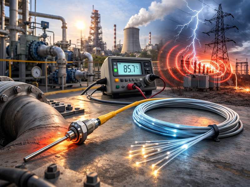
Fiber optic temperature sensing systems are valued for EMI immunity and long-distance monitoring, but long-term reliability is critical. This article examines why reliability testing matters and how it ensures stable performance over time.
Why Long-Term Reliability Matters
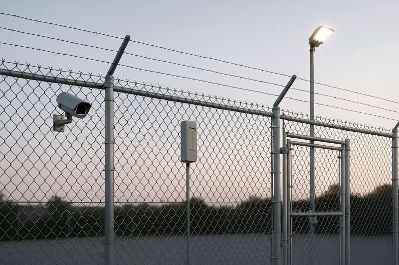
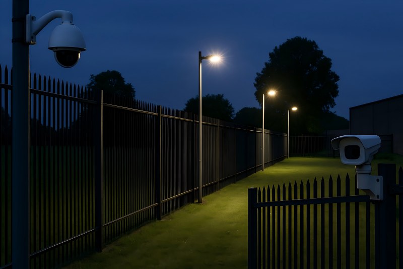
Fiber optic temperature systems are frequently deployed in critical and inaccessible environments, such as:
- High-voltage substations
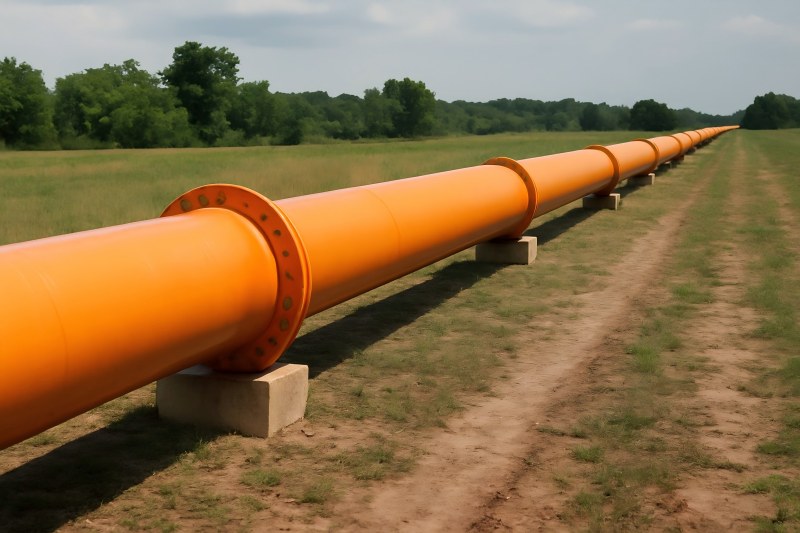
- Underground tunnels and pipelines
- Nuclear and thermal power plants
- Offshore platforms
- Rail and metro infrastructure
In these applications, sensor failure can lead to undetected overheating, false alarms, or costly shutdowns. Unlike conventional electrical sensors that may be replaced periodically, fiber optic systems are often embedded permanently, making long-term reliability essential.
Key drivers for reliability testing include:
- Ensuring measurement stability over decades
- Minimizing drift and recalibration needs
- Predicting service life under harsh conditions
- Meeting industry standards and certifications
- Reducing the total cost of ownership (TCO)
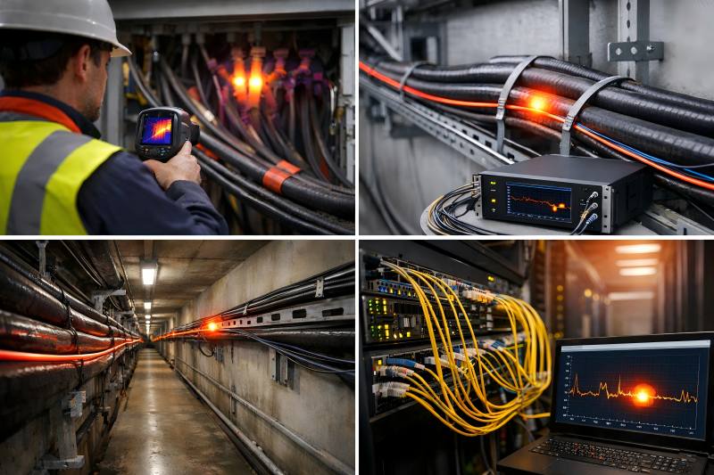
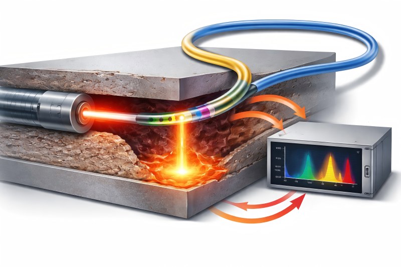
Core Components Subject to Reliability Testing
A fiber optic temperature system is not a single component but a system of interacting elements, each with unique aging mechanisms.
| Component | Function | Reliability Concern |
| Optical fiber | Temperature sensing medium | Coating degradation, attenuation increase |
| Sensing element (FBG, Raman, phosphor, FP) | Temperature encoding | Drift, fatigue, contamination |
| Connectors & splices | Signal continuity | Insertion loss, moisture ingress |
| Interrogator unit | Signal processing | Laser aging, electronics failure |
| Cables & sheathing | Environmental protection | Chemical, UV, and mechanical damage |
Long-term testing must evaluate both individual components and the integrated system.
Major Long-Term Failure Mechanisms
Understanding failure mechanisms is the foundation of reliability testing.
Optical Fiber Aging
Although silica fibers are chemically stable, long-term exposure to heat, radiation, or chemicals can cause:
- Increased attenuation
- Micro-crack propagation
- Coating embrittlement
- Hydrogen-induced losses
Sensor Drift
Temperature sensors may experience gradual drift due to:
- Refractive index changes
- Mechanical stress relaxation
- Grating or cavity aging
- Phosphor material degradation
Environmental Stress
External factors that accelerate aging include:
- Thermal cycling
- High humidity or condensation
- Chemical corrosion
- Vibration and mechanical fatigue
Interrogator Degradation
Electronic and optoelectronic components degrade over time:
- Laser wavelength drift
- Reduced signal-to-noise ratio (SNR)
- Power supply aging
- Component solder fatigue
Types of Long-Term Reliability Tests
Reliability testing combines accelerated laboratory tests with real-world field validation.
Accelerated Aging Tests
Accelerated tests simulate years of operation within a shorter timeframe.
| Test Type | Purpose | Typical Conditions |
| High-temperature aging | Evaluate thermal stability | 85–300 °C for 1,000–10,000 h |
| Thermal cycling | Stress expansion and contraction | −40 °C to +150 °C |
| Humidity exposure | Assess moisture resistance | 85 °C / 85% RH |
| UV exposure | Outdoor durability | UV-A / UV-B lamps |
| Chemical immersion | Corrosion resistance | Oils, acids, solvents |
Results are extrapolated using Arrhenius or Eyring models to predict service life.
Mechanical Performance Testing
Mechanical integrity is essential for installations subject to vibration or movement.
- Bend fatigue testing
- Tensile strength retention
- Vibration and shock testing
- Crush and abrasion resistance
| Parameter | Typical Requirement |
| Minimum bend radius | ≥10× cable diameter |
| Tensile load | 1,000–3,000 N |
| Vibration | IEC 60068 standards |
| Shock | Up to 50 g |
Optical Performance Stability Testing
Measurement accuracy must remain stable over time.
| Metric | Test Objective |
| Temperature accuracy | Drift < ±0.1 °C/year |
| Repeatability | Stable readings over cycles |
| Resolution | No degradation over time |
| Signal attenuation | <0.02 dB/km/year |
These tests often run continuously for months or years.
Distributed Temperature Sensing (DTS) Reliability Testing
DTS systems present unique challenges due to their long sensing range.
Fiber Length Stability
Testing verifies performance over tens of kilometers, focusing on:
- Attenuation growth
- Raman signal stability
- Spatial resolution consistency
Raman Scattering Stability
Because DTS relies on the ratio of Stokes and Anti-Stokes signals, reliability testing examines:
- Laser pulse stability
- Backscatter intensity consistency
- Temperature coefficient stability
| DTS Parameter | Long-Term Target |
| Temperature drift | ≤ ±1 °C over 10 years |
| Spatial resolution | No degradation |
| Measurement repeatability | ±0.5 °C |
| Fiber lifetime | >25 years |
Field Reliability and Long-Term Deployment Studies
Laboratory tests alone are insufficient. Field testing validates performance under real conditions.
Pilot Installations
Manufacturers deploy systems in:
- Power substations
- Oil pipelines
- Rail tunnels
These sites provide long-term data on:
- Environmental exposure
- Installation-induced stress
- Maintenance requirements
Continuous Monitoring Data
Reliability is evaluated through:
- Trend analysis
- Drift detection
- Alarm consistency
- Failure statistics
Standards and Qualification Frameworks
Long-term reliability testing is guided by international standards.
| Standard | Scope |
| IEC 61757 | Fiber optic sensor performance |
| IEC 60068 | Environmental testing |
| Telcordia GR-20 / GR-326 | Fiber and connector reliability |
| IEEE 1613 | Power utility environments |
| ISO 9001 | Quality management |
Compliance ensures repeatable, auditable, and comparable results.
Data Analysis and Lifetime Prediction
Reliability testing produces large datasets that must be analyzed correctly.
Statistical Methods
Common techniques include:
- Weibull analysis
- Mean Time Between Failures (MTBF)
- Confidence interval modeling
- Lifetime Estimation Models
| Model | Application |
| Arrhenius | Thermal aging |
| Eyring | Multi-stress environments |
| Coffin–Manson | Thermal fatigue |
| Miner’s rule | Cumulative damage |
These models translate accelerated test data into real-world lifetime predictions.
Maintenance and Recalibration Strategy Validation
Long-term testing also validates maintenance intervals.
| System Type | Typical Recalibration Interval |
| FBG systems | 5–10 years |
| DTS systems | 10–15 years |
| Fluorescence sensors | Minimal |
| Fabry–Perot sensors | 5–10 years |
Well-designed systems often achieve maintenance-free operation for over a decade.
Emerging Trends in Reliability Testing
Reliability testing continues to evolve alongside technology.
Key trends include:
- AI-driven drift detection
- Digital twin-based aging simulation
- Multi-parameter reliability testing (temperature + strain + vibration)
- Smaller, more stable laser sources
- Predictive maintenance analytics
These advances reduce uncertainty and further extend system lifetime.
Long-term reliability testing ensures fiber optic temperature systems deliver durable, low-maintenance performance in demanding environments, making it essential for long-term, mission-critical monitoring.