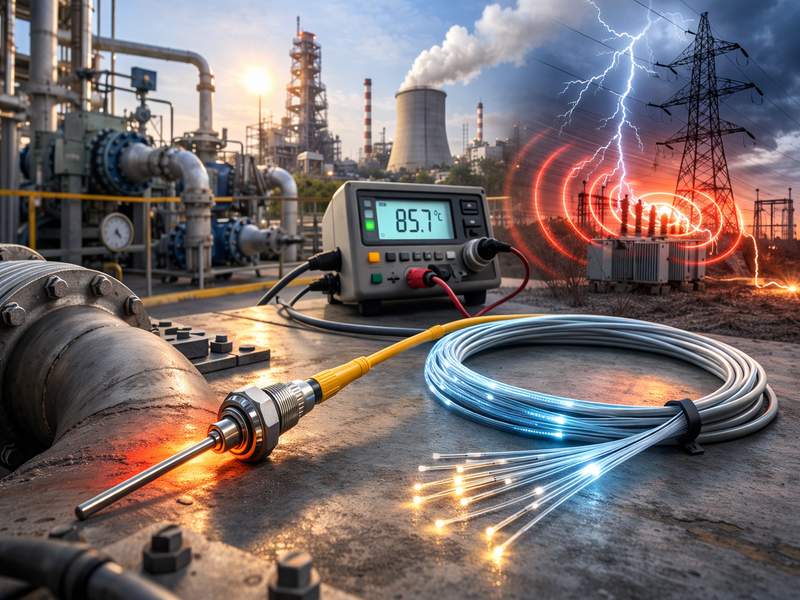
Fiber optic temperature sensors are now a key measurement solution in industries that demand high accuracy, safety, and reliability. Unlike conventional electrical temperature sensors, fiber optic sensors use light instead of electricity, making them immune to electromagnetic interference and suitable for extreme or hazardous environments.
This article provides a deep technical explanation of how fiber optic temperature sensors work, the core sensing mechanisms, different sensor types, and where each technology is best applied.
What Is a Fiber Optic Temperature Sensor?
A fiber optic temperature sensor measures temperature by monitoring how changes in heat affect light transmission within an optical fiber. The sensor consists of:
- A light source
- An optical fiber acting as the sensing medium
- A detector/interrogator that interprets the returned signal
Because optical fibers are dielectric (non-conductive), these sensors are inherently safe in high-voltage, explosive, or electromagnetically noisy environments.
Fundamental Working Principle
The working principle of fiber optic temperature sensors is based on the fact that temperature affects optical properties, such as:
- Refractive index
- Optical path length
- Light wavelength
- Light scattering intensity
- Phase or frequency of light
When temperature changes, it alters how light travels through, reflects from, or scatters within the fiber. These changes are measured and converted into accurate temperature values.
Core Physical Effects Used:
- Thermal expansion
- Thermo-optic effect
- Inelastic scattering
- Optical interference
Main Fiber Optic Temperature Sensing Technologies
Fiber optic temperature sensors can be categorized by how temperature information is encoded in light.
Major Fiber Optic Temperature Sensing Technologies
| Technology | Measurement Principle | Temperature Encoding Method |
| Fiber Bragg Grating (FBG) | Wavelength shift | Reflected Bragg wavelength |
| Distributed Temperature Sensing (DTS) | Raman scattering | Backscattered light intensity |
| Interferometric Sensors | Phase change | Optical phase difference |
| Fluorescence-Based Sensors | Decay time | Fluorescence lifetime |
| Fabry–Perot Sensors | Cavity length change | Interference pattern shift |
Fiber Bragg Grating (FBG) Temperature Sensor Principle
How It Works
An FBG sensor contains a microscopic periodic structure (grating) inscribed inside the fiber core. This grating reflects a specific wavelength, referred to as the Bragg wavelength.
When temperature changes:
- The fiber expands or contracts
- The refractive index changes
- The reflected wavelength shifts proportionally
Advantages
- High accuracy
- Fast response
- Suitable for multi-point sensing
Limitations
Cross-sensitivity to strain (requires compensation)
Distributed Temperature Sensing (DTS) Working Principle
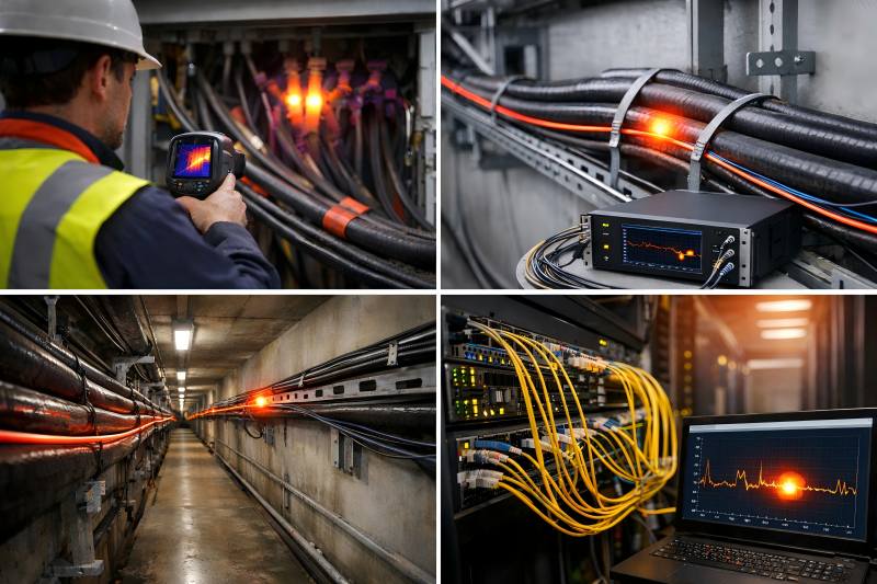
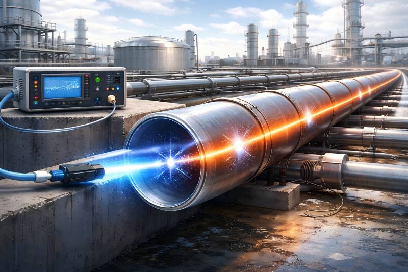
Distributed Temperature Sensing continuously monitors temperature along the full length of an optical fiber, often across distances of tens of kilometers.
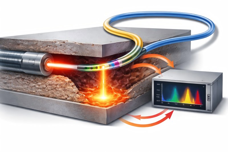
Raman Scattering Mechanism
A short laser pulse is sent into the fiber. As light interacts with the fiber material, Raman backscattering occurs, producing:
- Stokes signal (temperature-independent)
- Anti-Stokes signal (temperature-dependent)
- The intensity ratio between these signals determines the temperature at each point.
Interferometric Fiber Optic Temperature Sensors
Interferometric sensors rely on optical phase changes caused by temperature variations.
Common Types
- Mach–Zehnder
- Michelson
- Sagnac
Principle
Temperature alters the optical path length of one arm of the interferometer, causing a phase shift when compared to a reference arm. This phase difference is detected as interference fringes.
Key Characteristics
- Extremely high sensitivity
- Suitable for micro-temperature changes
- Complex signal processing required
Fluorescence-Based Fiber Optic Temperature Sensors
These sensors use temperature-dependent fluorescence decay time.
How It Works
- A phosphor material at the fiber tip is excited by light
- The material emits fluorescence
- The decay time of fluorescence changes with temperature
Key Advantage
- Insensitive to signal loss and fiber bending
- Excellent stability in harsh environments
Common Use
- Medical devices
- Power transformer winding monitoring
Fabry–Perot Fiber Optic Temperature Sensor Principle
A Fabry–Perot sensor consists of two reflective surfaces forming an optical cavity.
Temperature Effect
- Temperature changes cause cavity length expansion
- This shifts the interference pattern
- The shift is correlated to temperature
Benefits
- High resolution
- Compact design
- Suitable for point sensing
Comparison of Fiber Optic Temperature Sensor Types
| Sensor Type | Measurement Range | Accuracy | Response Time | Typical Applications |
| FBG | −200 to 300 °C | ±0.1 °C | ms | Power systems, aerospace |
| DTS (Raman) | −40 to 600 °C | ±1–2 °C | seconds | Pipelines, tunnels |
| Interferometric | Narrow | ±0.01 °C | ms | Scientific research |
| Fluorescence | −200 to 450 °C | ±0.5 °C | ms | Medical, transformers |
| Fabry–Perot | −50 to 400 °C | ±0.1 °C | ms | Industrial monitoring |
Advantages Over Traditional Temperature Sensors
Fiber optic temperature sensors outperform thermocouples and RTDs in several key areas:
- Electromagnetic immunity
- Electrical isolation
- Intrinsic safety
- Long-distance measurement
- Multiplexing capability
- Resistance to corrosion and moisture
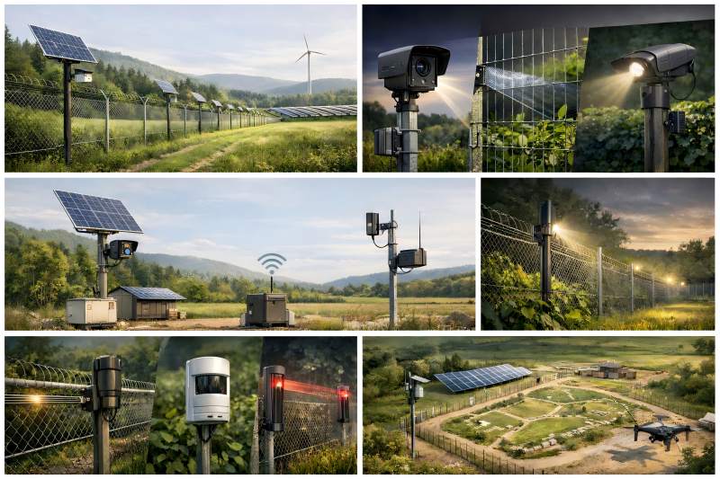
Environmental and Industrial Suitability
Fiber optic temperature sensors are ideal for:
- High-voltage environments
- Explosive atmospheres
- Strong electromagnetic fields
- Corrosive chemicals
- Remote or inaccessible locations
They are widely deployed in:
- Power generation
- Oil & gas
- Rail transportation
- Smart infrastructure
- Industrial automation
Signal Processing and Interrogation Systems
The interrogator is the brain of a fiber optic temperature sensing system. It performs:
- Light generation
- Signal demodulation
- Temperature calculation
- Data transmission
Advanced systems integrate:
- Digital signal processing (DSP)
- AI-assisted anomaly detection
- Real-time alarms
- SCADA or IoT platforms
Calibration and Accuracy Considerations
To ensure accuracy:
- Sensors are factory-calibrated
- Temperature-strain compensation may be required
- Environmental factors such as bending radius and aging must be considered
Future Trends in Fiber Optic Temperature Sensing
Key developments include:
- Higher spatial resolution DTS
- Multi-parameter sensing (temperature + strain + vibration)
- Smaller interrogators
- AI-driven predictive maintenance
- Integration with digital twins
The working principle of fiber optic temperature sensors is rooted in light–matter interaction, enabling precise temperature measurement without electrical conduction. Through technologies such as FBG, DTS, interferometric, fluorescence, and Fabry–Perot sensing, fiber optic temperature sensors provide unmatched safety, scalability, and performance.
As industries demand smarter, safer, and more connected monitoring solutions, fiber optic temperature sensing will continue to play a critical role in next-generation industrial and infrastructure systems.