Designing a strong fence is only half the job. If your security system layout leaves blind spots—areas that cameras, sensors, or lighting don’t properly cover—intruders will find and exploit them. A well-planned fence security system focuses on continuous, overlapping coverage so every meter of perimeter is monitored and verified.
This guide walks you through how to design or upgrade your fence security layout so blind spots are found and eliminated before criminals find them.
Start with a Perimeter Risk Assessment
Before placing a single camera or sensor, you need a clear understanding of the perimeter you’re protecting.
Key steps:
- Map the property: Create a scaled plan showing fence lines, corners, gates, access roads, parking areas, loading bays, and nearby buildings.
- Identify high-risk zones: Focus on secluded areas, poorly lit stretches, blind alleyways, and spots near public roads or neighboring buildings where intruders can hide or stage tools.
- Note environmental constraints: Trees, slopes, walls, containers, metal structures, and water can affect camera views, IR/microwave sensors, and RF interference.
- Check existing systems: Document current cameras, fence sensors, motion detectors, lighting, and alarm routes. Mark where alarms frequently occur and where incidents have already happened.
This assessment becomes the foundation for all layout decisions. It also helps you justify budget and technology choices later.
Understand Where Blind Spots Come From
Blind spots are not random; they usually come from predictable design issues. Recognizing these makes them easier to remove.
Common causes of fence blind spots:
- Camera fields of view that don’t overlap or are aimed incorrectly
- “Dead zones” directly under cameras or behind posts and columns
- Corners and turns where cameras or sensors don’t fully cover the angle
- Dark stretches of fence due to uneven lighting or burned-out fixtures
- Vegetation, parked vehicles, containers, or signage blocking sensors
- Elevation changes (slopes, mounds, ditches) affecting line-of-sight sensors
- Poorly routed cabling for fence-mounted systems creates gaps in detection
A good layout deliberately addresses each of these.
Quick Reference: Typical Blind Spot Sources & Fixes
| Blind Spot Source | Typical Cause | Primary Fix |
| Under cameras (“dead zone”) | Camera mounted too high/close | Overlapping camera or adjusted angle |
| Dark fence stretch | Poor lighting, spacing, or glare | Even overlapping lighting along the fence |
| Corners & gate posts | Single device tasked with two angles | Dedicated corner/gate camera or sensor |
| Vegetation & clutter | No clear zone near the fence | Maintain a vegetation-free strip |
| Sensor gaps on the fence | Incorrect zone lengths or routing | Re-segment sensors; follow manufacturer spec |
Segment the Perimeter into Independently Monitored Zones
Instead of treating the fence as one long line, divide it into zones—straight runs between corners, gates, or key structures. Many regulatory and design guides recommend segmenting the perimeter so each zone can be independently monitored and alarmed.
For each zone, define:
- Zone length: Based on sensor/cable limitations and camera performance.
- Zone type: Straight run, corner, gate, or high-risk section.
- Target detection method: Fence-mounted sensors, buried cable, IR beams, or a combination.
- Assessment method: Fixed cameras, PTZ (pan-tilt-zoom) cameras, thermal cameras, or on-site response.
Zoning makes it easier to pinpoint alarm locations, reduces the chance of long, unmonitored stretches, and simplifies maintenance and troubleshooting.
Design Overlapping Camera Coverage
Cameras are your primary verification tool, so their placement is critical for eliminating blind spots.
Use Overlapping Fields of View
Best-practice guidance recommends overlapping camera coverage zones so one camera’s field of view includes the blind spot of the next camera.
Practical tips:
- Overlap 10–20% of coverage: Where one camera’s view ends, the next should already be watching.
- Cover camera “dead zones”: The area directly below each camera is usually a blind spot; ensure the next camera covers this region.
- Use complementary lenses: Combine wide-angle cameras (for general perimeter tracking) with narrow-angle or PTZ cameras (for high-detail identification at gates and choke points).
Optimize Height and Angle
Camera height and angle have a huge impact on coverage:
- Mount cameras at a sufficient height (e.g., 4 m or higher on poles or buildings) and tilt them downwards to reduce sky and maximize ground coverage.
- Aim fields of view parallel to the fence line and perpendicular to expected intruder movement—this gives longer tracking time and better detection probability.
- Avoid placing cameras so close to the fence that they only see a narrow strip; you want enough depth to track movement on both sides.
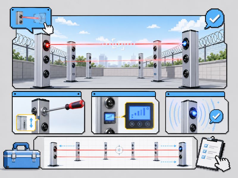
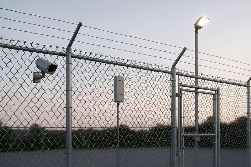
Plan Fence Sensor Layout for Continuous Detection
Fence-mounted perimeter intrusion detection systems (PIDS/FIDS) can detect climbing, cutting, or lifting attempts along the fence line. To eliminate blind spots, the sensor layout must be as continuous as the fence itself.
Follow Sensor Zoning and Cable Rules
Guidance for barrier-mounted systems generally recommends:
- Only the sensor cable should be mounted on the fence; other cabling should, where possible, be at a stand-off to reduce vulnerability and noise.
- Design clear detection zones and keep within the maximum zone length recommended by the manufacturer to maintain sensitivity and avoid weak spots.
- Use a clear zone along the fence—free of vegetation, debris, and adjacent objects—to prevent interference with sensor performance and reduce false alarms.
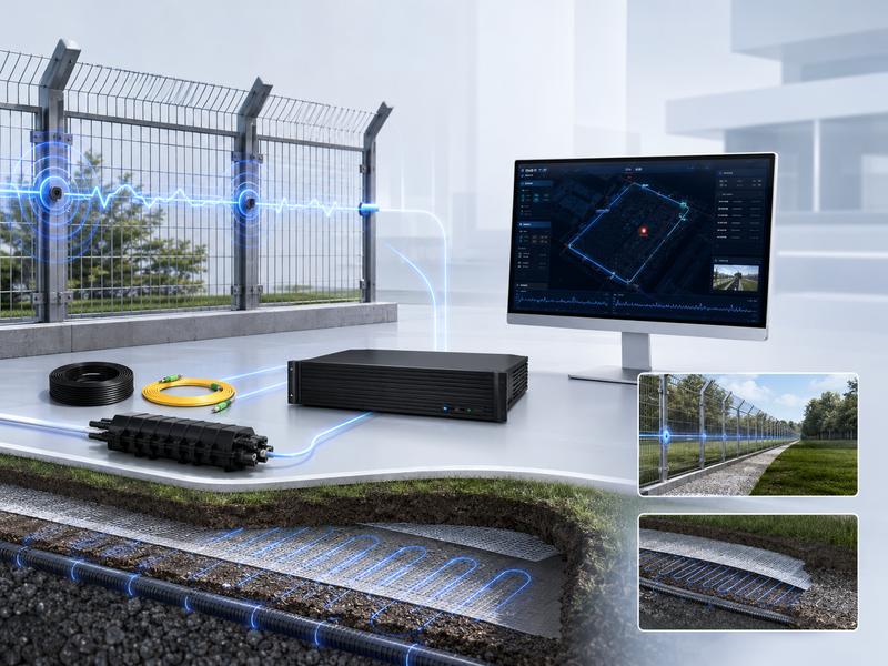
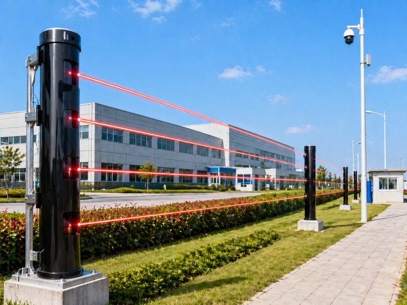
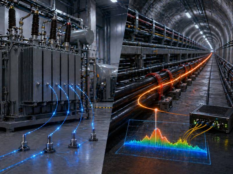
Combine Technologies for High-Risk Areas
A dual-layer approach—combining fence-mounted detection with secondary technologies (e.g., buried cable, IR beams, radar, or thermal cameras)—can cover blind spots in very high-risk zones or complex terrain.
Examples:
- Fence-mounted sensor + thermal camera at remote, dark perimeter stretches
- Fence-mounted sensor + microwave barrier across open ground near a road
- Fence-mounted sensor + active IR beams at vehicle gates and side entrances
Layering ensures that if one technology is temporarily degraded (e.g., by heavy wind or rain), another still provides coverage.
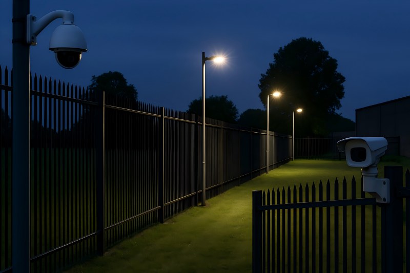
Use Strategic Lighting to Remove Dark Zones
Even the best cameras and sensors struggle when visibility is poor. Proper perimeter lighting is essential to remove hiding places and support video analytics.
Key principles:
- Uniform illumination: Avoid “spotty” pools of light separated by darkness. Even, continuous lighting reduces shadows and hiding places.
- Overlap light beams: Space lights so each beam reaches into the next, similar to camera overlap, to eliminate dark gaps along the fence.
- Control glare: Too much glare reduces camera image quality and makes it hard for guards to see. Select fixtures and angles that light the fence line, not the cameras’ lenses.
- Harden fixtures: Mount lights high enough and slightly off the fence line to make tampering harder.
Where energy use is a concern, consider LED fixtures, motion sensors, and smart controls to maintain security while managing costs.
Pay Special Attention to Corners, Gates, and Obstacles
Most real-world breaches occur at weak points: corners, gates, and cluttered sections.
Corners and Turns
Corners create natural blind angles:
- Use dedicated corner cameras or dual cameras mounted back-to-back to see both sides.
- Ensure fence sensors are properly terminated and re-started around corners so detection doesn’t “thin out.”
- Clear vegetation and objects near corners to avoid hiding spots.
Gates and Vehicle Entrances
Gates concentrate traffic and attacker interest:
Provide dedicated, higher-resolution camera views aimed at the gate from both inside and outside.
Implement redundant detection: fence-mounted sensors on gate frames plus ground loops, IR beams, or radar overlapping the gate zone.
Ensure lighting is excellent here; license plates and faces should be clearly visible.
Obstacles and Site Features
Stores, containers, parked trucks, billboards, and dense shrubs can all create blind spots:
Keep a “sterile zone” directly adjacent to the fence—no permanent storage or tall vegetation.
Re-aim cameras and adjust sensor zones whenever large objects are moved in or out of the area.
Validate Coverage with Testing, Not Just Drawings
Even the best layout on paper must be proven in the field.
Recommended practices:
- Walk-tests: Have staff walk the perimeter, especially high-risk zones, at day and night. Verify that cameras, sensors, and lights perform as expected in real conditions.
- Scenario drills: Simulate climbing, cutting, crawling, and gate breaches at different points to confirm alarms trigger correctly and response procedures work.
- Video review: Record test events and confirm that operators can clearly identify people, direction of movement, and key details (clothing, plate numbers).
- Document and adjust: Maintain diagrams of the final layout and record any changes. Update device positions when adjustments are made so future teams know the current design.
Regularly scheduled testing—quarterly or semi-annually—keeps the system effective as the environment and usage patterns change.
Maintain and Continuously Improve the Layout
A layout that is perfect in year one can develop blind spots by year three if not maintained.
Long-term measures:
- Vegetation control: Trees and shrubs grow into cameras and sensors, creating shadows and false alarms. Add maintenance of the “clear zone” to your grounds schedule.
- Inspect mounts and brackets: Wind and vibration can slowly move cameras and sensors, shifting coverage. Check alignment and tighten hardware regularly.
- Replace or upgrade aging equipment: Older analog cameras or worn sensors may no longer meet your coverage or resolution needs.
- Monitor alarm data: Repeated “no-event” alarms in certain zones can indicate environmental problems or layout issues. Alarm analytics can highlight weak spots.
- Train staff: Continuous training ensures operators and maintenance teams understand which areas are critical and how the layout is meant to function.
If your system includes advanced fence intrusion detection system hardware from a specialist provider (for example, a brand like Gato Security), work with their engineering support to periodically review the layout against new best practices and evolving threats.
Bringing It All Together
Eliminating blind spots in a fence security system is not about buying a single “magic” device. It’s about design:
- A perimeter divided into intelligently monitored zones
- Cameras with overlapping fields of view and optimized angles
- Fence sensors laid out in continuous, well-defined detection zones
- Uniform, glare-controlled lighting that removes dark hiding spots
- Special attention to corners, gates, and cluttered areas
- Regular testing, documentation, and maintenance to keep coverage tight over time
When you treat layout as a living design—reviewed after changes in buildings, vegetation, and threat levels—you move from a vulnerable, patchwork perimeter to a true “zero blind spot” fence security system.