Electrical cables power critical systems in data centers, plants, substations, and transport hubs, often under heavy loads. As energy demands rise, overheating has become a major fire risk, leading to outages, damage, compliance issues, and safety hazards.
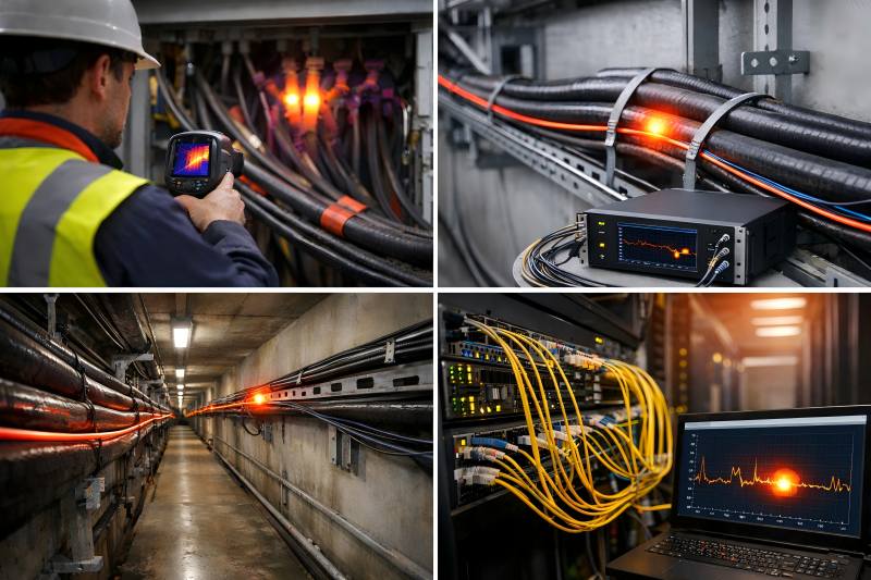
Traditional methods like thermal scans and point sensors often miss early hotspots and lack continuous monitoring. Fiber optic temperature systems provide real-time, continuous detection along the entire cable, enabling early fire prevention.
Why Cable Fires Occur
Electrical cables can overheat for many reasons. Understanding these causes is essential to appreciating why advanced monitoring is necessary.
Common Causes of Cable Overheating
- Overloading: Current beyond cable design capacity raises conductor temperature.
- Loose connections: Poor terminations create resistance, generating heat.
- Insulation degradation: Aging or damaged insulation increases leakage and heat.
- Ambient conditions: High local temperature or poor ventilation reduces heat dissipation.
- Mechanical damage: Crush or impact reduces thermal performance.
- Faults: Arcing and short circuits produce localized hotspots.
Uncontrolled heat can degrade insulation and conductor integrity, leading to short circuits, combustible arcing, or ignition of surrounding materials — all precursors to cable fires.
Traditional Overheating Detection Methods and Their Limits
Before reviewing fiber optic temperature systems, it’s useful to understand standard methods and why they fall short in preventing cable fires.
| Method | How It Works | Limitations |
| Manual Thermography | Periodic thermal imaging scans by technicians | Only as good as inspection frequency; misses transient events; labor-intensive |
| Point Temperature Sensors | Fixed RTDs or thermocouples at select points | Doesn’t cover the entire cable length; hotspots between sensors go undetected |
| Current Monitoring | Detects overcurrent conditions via ammeters | Only infers temperature; may not detect resistive heating or insulation failure |
| Visual Inspection | The technician looks for signs of damage | Reactive, not continuous; misses hidden or early-stage thermal issues |
| Smoke/Flame Detectors | Standard fire alarm systems | Only detects fire after combustion has started; too late for prevention |
Because these technologies either monitor indirectly, are intermittent, or have low spatial coverage, a gap remains in early, continuous, and accurate temperature monitoring of cable systems. That gap is exactly what fiber optic temperature monitoring fills.
How Fiber Optic Temperature Monitoring Works
Fiber optic temperature systems leverage the physical properties of optical fibers (typically using backscatter phenomena such as Raman or Brillouin scattering) to measure temperature along the length of a fiber cable.
Principles of Operation
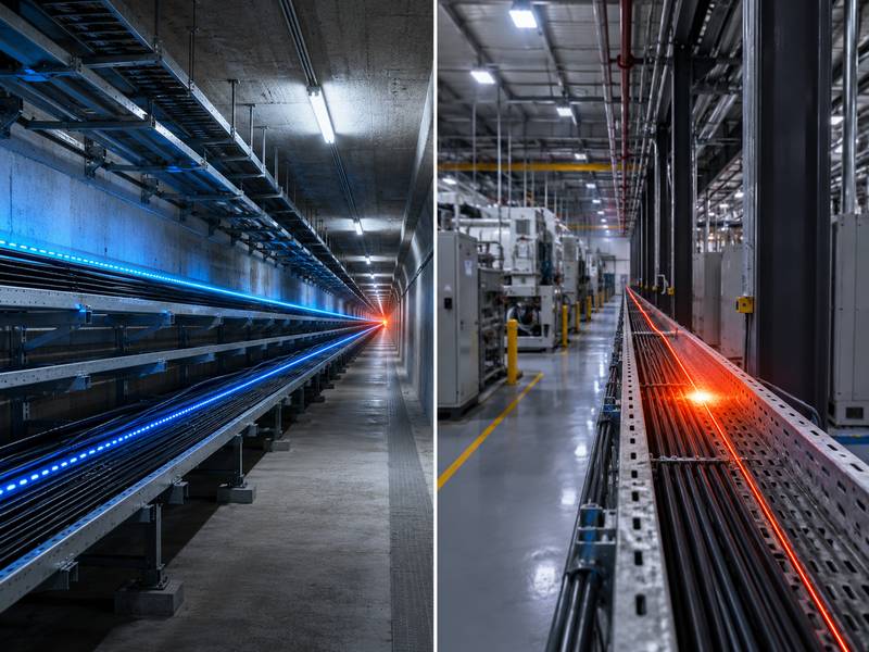
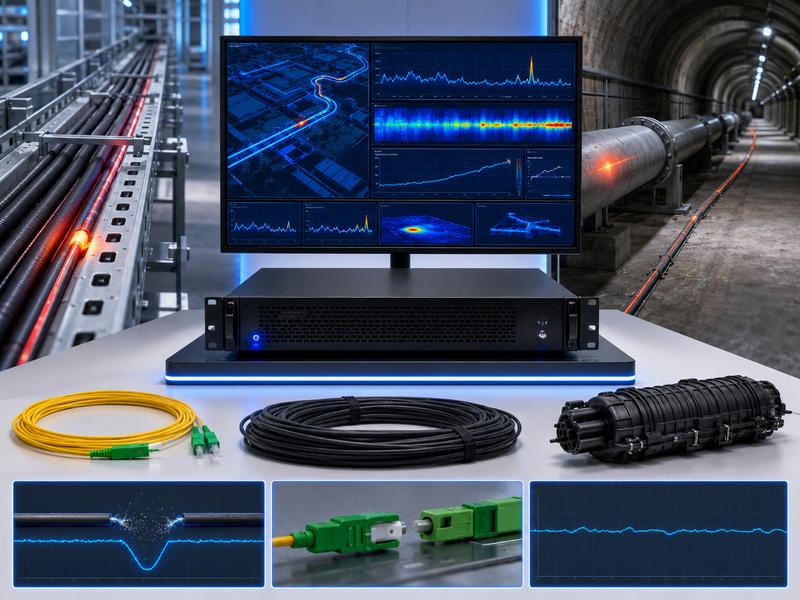
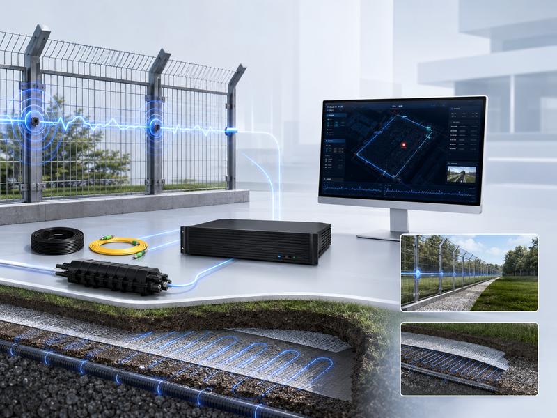
An optical fiber is laid alongside or integrated into the power/data cable infrastructure. A central interrogator unit sends laser pulses down the fiber. As the light travels, some of it backscatters due to inherent microscopic irregularities in the fiber. Temperature affects the backscattered signal’s properties.
By examining these modifications, the system is able to:
- Check the temperature at each location along the fiber.
- Identify precise locations of hotspots
- Generate continuous, real-time temperature profiles
This process is typically referred to as Distributed Temperature Sensing (DTS).
Types of Fiber Optic Temperature Systems
| System Type | Description | Typical Accuracy |
| Raman-based DTS | Uses Raman backscatter to measure temperature | ±1°C to ±2°C |
| Brillouin-based DTS | Uses Brillouin scattering for temperature and strain | ±0.5°C to ±1.5°C |
| Fiber Bragg Grating (FBG) | Uses embedded gratings for precise point measurements | ±0.1°C |
Depending on the necessary spatial resolution, measurement range, and cost, each strategy has a place.
Why Fiber Optic Systems Are Ideal for Cable Fire Prevention
Fiber optic temperature systems substantially mitigate several shortcomings of traditional methods. Below are key benefits:
Continuous, Real-Time Monitoring
Unlike periodic surveys, fiber optic systems provide instant temperature data. Temperature rise trends are detected early, offering time to respond before conditions worsen.
Distributed Detection Along Entire Cable Length
Where traditional point sensors monitor a handful of locations, fiber optics monitor every meter (or even centimeter) of cable — from meter zero to kilometer marks.
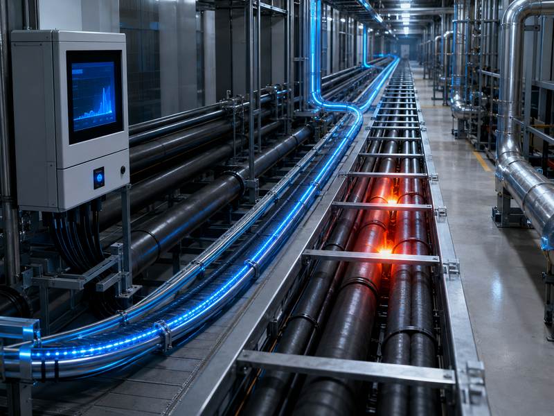
Early Warning of Hotspots
Localized overheating due to loose connections or insulation failure can be identified well before insulation breakdown or combustible conditions occur.
Non-Conductive and Immune to Electromagnetic Interference
Optical fibers are dielectric and not affected by electrical noise. They are safe to install near high voltage cables.
Integration with Automated Protection Systems
Fiber optic systems can be tied into SCADA, BMS (Building Management Systems), or industrial PLCs — triggering alarms, automated shutdowns, or cooling responses.
Scalability
Whether a small data room or a long high-voltage feeder tunnel, the same technology scales from tens of meters to tens of kilometers.
Key Applications of Fiber Optic Temperature Monitoring
The following sectors benefit significantly from fiber optic temperature systems:
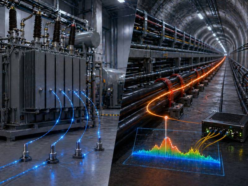
Electrical Distribution and Substations
High current feeders, switchgear connection cables, and transformer bushings are common hotspots in substations. DTS systems can pinpoint heaters before faults occur.
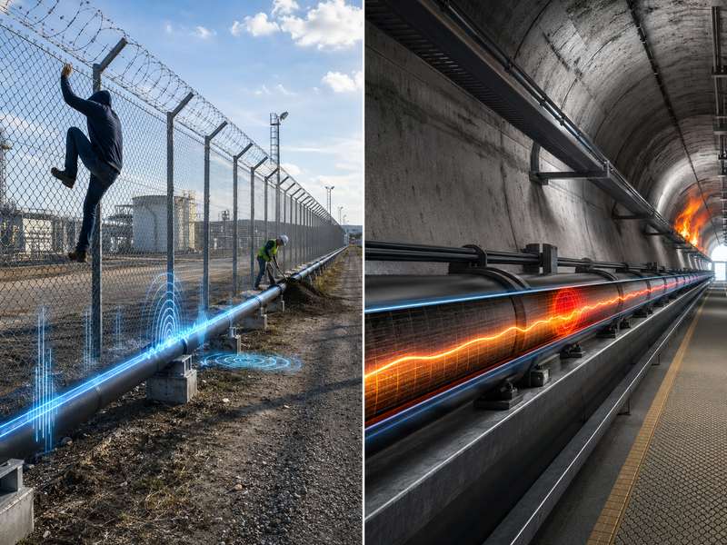
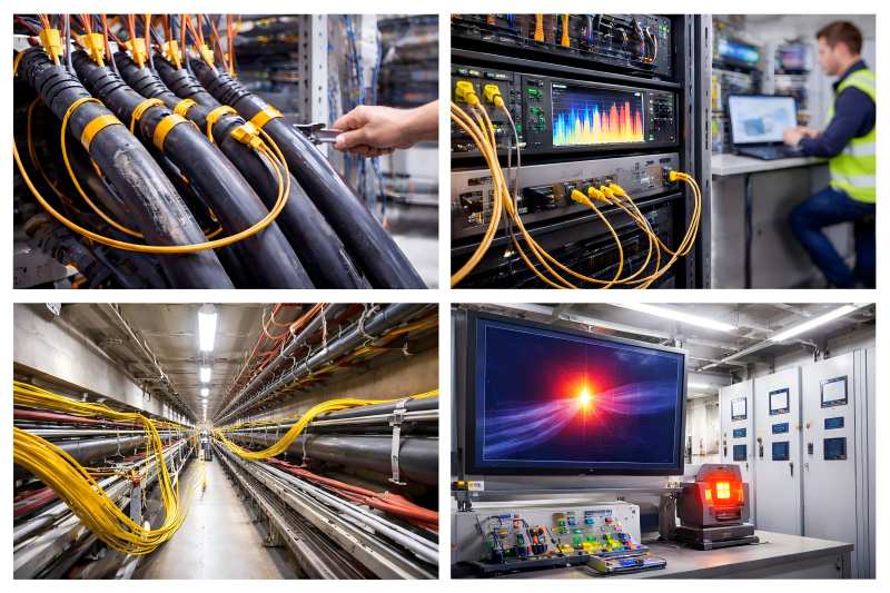
Tunnel and Infrastructure Power Cables
Transport tunnels often bundle power cables without easy access for inspection. Continuous temperature monitoring ensures safety in environments where manual access is limited.
Data Centers and IT Infrastructure
Data center power distribution and UPS cabling must remain within thermal design limits. Early overheating detection prevents outages and fire risk.
Industrial Plants
Manufacturing environments with high ambient temperatures and heavy machinery loading require robust monitoring of critical power cables.
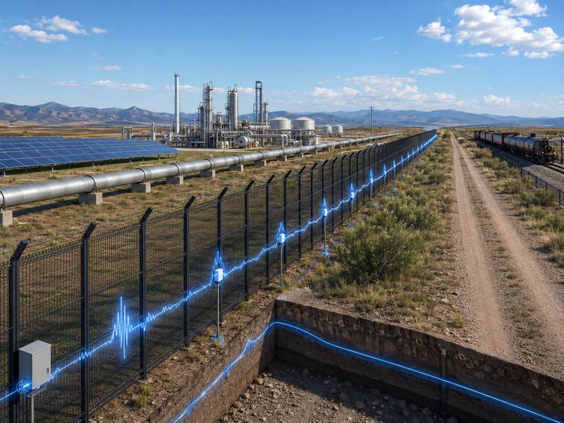
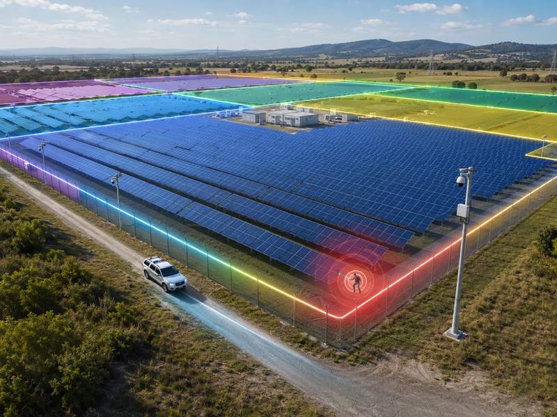
Renewable Energy Systems
Wind farms, solar installations, and battery storage sites often have remote or distributed cable networks that benefit from centralized temperature monitoring.
Implementing Fiber Optic Temperature Monitoring for Cable Safety
To make the most of fiber optic systems, proper planning and integration are essential. Consider these key steps.
Cable and Fiber Installation Best Practices
Place the fiber as close as possible to the cable surface to ensure accurate temperature measurement.
- Use protective conduits or clips designed for cable trays and duct banks.
- Avoid sharp bends; maintain minimum bend radius specifications of the optical fiber.
- In high-temperature zones, consider fire-rated fiber jackets.
System Configuration and Calibration
- Define alarm thresholds based on cable specification and environmental conditions.
- Calibrate the system with baseline measurements when cables are at known temperatures.
- Configure multi-zone monitoring for complex cable layouts.
Integration with Control Systems
- Connect fiber optic alarms to Building Management Systems (BMS), SCADA, or industrial PLCs.
- Implement automated responses like fan activation, load shedding, or emergency shutdowns upon threshold breach.
- Leverage data logging for trend analysis and predictive maintenance.
Maintenance and Testing
Perform routine integrity checks of fiber continuity.
Validate alarm response by simulating controlled temperature rises.
Maintain documentation of fiber routes and system configurations.
Case Studies: Prevention in Action
Case Study 1: Preventing Overheating in a Substation Cable Bank
A utility installed a Brillouin-based DTS along critical substation feeders. Within weeks, the system detected a slow temperature rise at one termination point. Investigation revealed a loose lug — tightened before insulation breakdown occurred. The cost of tightening was minor compared to the avoided damage.
Case Study 2: Data Center Cable Fire Averted
In a high-density data center, sudden load increases triggered a hotspot in a power feeder. The fiber optic system sent an alarm to the BMS, which automatically increased cooling airflow and alerted technicians. Within minutes, the risk was mitigated.
Quantifying the Benefits
Results with and without fiber optic temperature monitoring are contrasted below.
| Outcome Metric | Without Fiber Optic Monitoring | With Fiber Optic Monitoring |
| Detection Time | Occasional thermal scans only | Continuous real-time alerts |
| Hotspot Localization | Poor (general area only) | Precise to meter/centimeter |
| False Alarms | Moderate (due to indirect methods) | Low (direct temperature measurement) |
| Fire Risk Reduction | Reactive | Proactive prevention |
| Maintenance Cost | High (emergency repairs) | Lower (planned interventions) |
| Outage Incidents | Higher | Significantly reduced |
Addressing Common Concerns
Cost of Implementation
Initial costs are higher than point temperature sensors, but the total cost of ownership is lower when factoring in reduced outages, avoided equipment damage, and extended cable life.
Complexity
Modern fiber systems are plug-and-play with intuitive software dashboards. Training is required but achievable with vendor support.
Compatibility with Existing Infrastructure
Fiber optic systems are compatible with new and retrofit installations. Trays, conduits, and existing cable routes can host fiber with minimal disruption.
Future of Cable Fire Prevention
As electrical networks become denser and more critical, real-time distributed monitoring will be standard practice rather than optional. Advances in fiber sensing continue to make systems more accurate, cost-effective, and integrated with artificial intelligence and predictive analytics.
Emerging features include:
- Machine learning trend analysis for fault prediction
- Combined strain and temperature sensing to detect mechanical stresses
- Integration with digital twins for dynamic simulation and risk modeling
Best Practices Summary
When deploying fiber optic temperature systems for cable fire prevention:
- Design early: Incorporate monitoring in planning stage
- Select appropriate technology (Raman, Brillouin, or FBG) based on spatial and accuracy needs
- Install fiber close to cables and protect against environmental hazards
- Integrate alarms with operational systems (BMS, SCADA)
- Calibrate and verify thresholds based on real-world conditions
- Use data for predictive maintenance — not just reactive alarms
Cable fire prevention requires continuous, accurate temperature monitoring along the entire cable. Traditional sensors are insufficient. Fiber optic systems provide real-time, distributed detection of hotspots for early intervention.
Though costlier upfront, they prevent failures, repairs, and downtime — forming a reliable foundation for resilient electrical infrastructure.