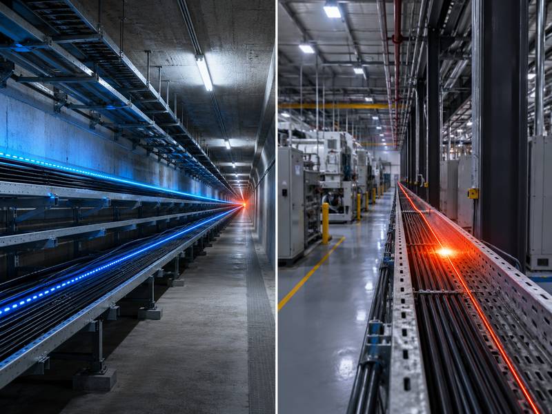
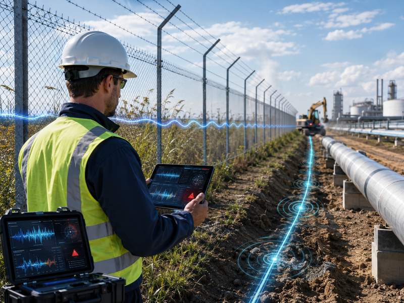
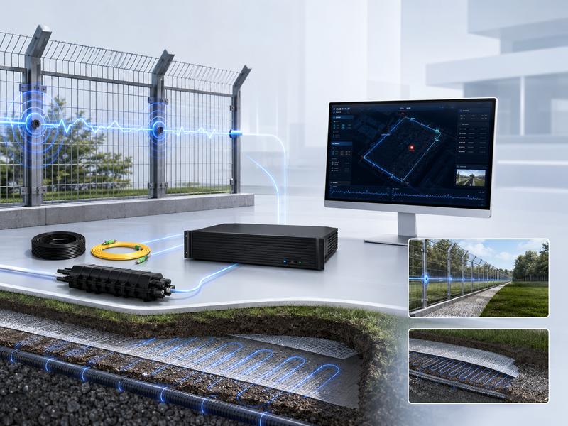
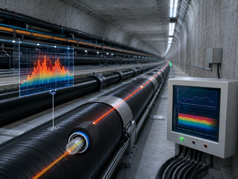
Fiber optic temperature monitoring is used in cables, tunnels, pipelines, energy facilities, industrial plants, data centers, and fire-risk areas for continuous temperature detection and early overheating warnings.
However, false alarms can reduce trust, increase inspection costs, and disrupt operations. Reducing them requires proper design, installation, signal processing, environmental compensation, smart alarm logic, and regular maintenance.
Understanding False Alarms in Fiber Optic Temperature Monitoring
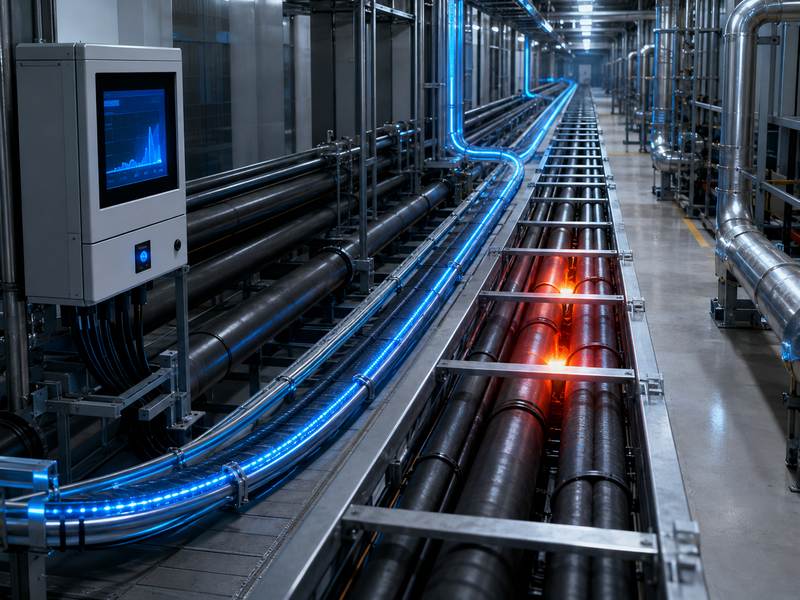
Fiber optic temperature monitoring systems usually use optical fibers as sensing elements. The system detects temperature changes by analyzing optical signals along the fiber. In distributed temperature sensing, one fiber cable can monitor thousands of temperature points over long distances. This makes it highly suitable for large-scale assets such as cable tunnels, oil pipelines, conveyor belts, transformer areas, and industrial storage zones.
False alarms can happen when the system misinterprets normal temperature fluctuation, installation stress, signal noise, or environmental interference as a real abnormal condition.
Common false alarm situations include:
- Alarm triggered by a short-term temperature fluctuation
- Alarm caused by poor fiber cable installation
- Alarm from mechanical stress or fiber bending
- Alarm caused by incorrect zone configuration
- Alarm triggered by background heat sources
- Alarm caused by unstable system calibration
- Alarm from communication or data processing errors
To reduce false alarms, the system should be treated as a complete solution, not only a sensing device.
Main Causes of False Alarms
Before improving alarm accuracy, it is important to understand where false alarms come from. In many projects, false alarms are not caused by the fiber optic technology itself, but by poor design, poor installation, or unsuitable alarm settings.
| Cause of False Alarm | Typical Scenario | Impact on Monitoring Accuracy |
| Improper alarm threshold | The fixed temperature limit is too low | Normal temperature rise may trigger alarms |
| Poor cable installation | Fiber cable is bent, squeezed, or loosely fixed | Signal distortion or unstable readings |
| Environmental heat sources | Sunlight, hot pipes, machines, and ventilation outlets | Localized heat may be misjudged as a danger |
| Signal noise | Weak optical signal or poor connector quality | Unstable temperature data |
| Incorrect zone division | One alarm zone covers different environments | Hard to identify real abnormal conditions |
| Lack of trend analysis | The system reacts to instant temperature peaks | Short-term changes become alarms |
| Insufficient maintenance | Dirty connectors, aging cables, loose joints | Long-term system reliability decreases |
Understanding these causes helps engineers choose the right technical measures during design, installation, and operation.
Use Dynamic Alarm Thresholds Instead of Fixed Limits
One of the most effective ways to reduce false alarms is to avoid relying only on fixed temperature thresholds. A fixed threshold means the alarm is triggered when the temperature exceeds a preset value, such as 60°C or 80°C. This method is simple, but it may not work well in complex environments.
For example, the normal temperature of a power cable in summer may be much higher than in winter. A tunnel section close to ventilation equipment may have a different background temperature from an underground section. If the same fixed threshold is applied to all areas, false alarms may increase.
A better method is to use dynamic alarm thresholds. These thresholds consider background temperature, historical data, equipment operating conditions, and temperature change rate.
| Alarm Method | Description | False Alarm Risk | Best Use Case |
| Fixed temperature threshold | Alarm triggers when the temperature exceeds a set value | Medium to high | Simple environments |
| Differential temperature alarm | Compares the temperature difference between nearby points | Lower | Cable tunnels, pipelines, and long-distance routes |
| Rate-of-rise alarm | Detects how fast the temperature increases | Lower | Fire-risk areas, overheating detection |
| Dynamic baseline alarm | Compares current data with the historical normal range | Low | Complex industrial environments |
| Multi-condition alarm | An alarm requires several conditions to be met | Very low | High-security or high-value assets |
Dynamic alarm logic can identify abnormal changes more accurately because it focuses on the temperature behavior, not only the absolute temperature value.
For example, a temperature of 55°C may be normal for a heavily loaded power cable, but dangerous for a storage area. Similarly, a temperature rise from 30°C to 50°C within two minutes may be more dangerous than a stable temperature of 55°C over several hours.
Apply Temperature Trend Analysis
False alarms often happen when the system reacts too quickly to temporary temperature changes. In many real applications, short-term temperature spikes may be caused by sunlight exposure, temporary equipment operation, hot air movement, or brief load changes.
Temperature trend analysis helps the system distinguish between temporary fluctuation and real abnormal development.
A reliable system should analyze:
- Current temperature
- Historical temperature
- Temperature rise speed
- Temperature duration
- Temperature difference between adjacent points
- Repeated abnormal patterns
For example, if the temperature rises sharply and continues increasing, it may indicate overheating or fire risk. However, it can be a transient situation if the temperature raises momentarily before returning to normal.
| Temperature Pattern | Possible Meaning | Recommended Alarm Response |
| Sudden short spike | Temporary heat source or signal fluctuation | Record event, delay alarm |
| Slow continuous rise | Equipment load increase or developing fault | Warning alarm |
| Fast continuous rise | Fire risk or serious overheating | High-priority alarm |
| Local hot spot with stable surroundings | Real localized abnormal heating | Zone alarm and inspection |
| Similar rise across a large area | Environmental temperature change | Adjust baseline or issue a low-level alert |
The technique can cut down on pointless alerts while still identifying actual threats early by examining temperature changes.
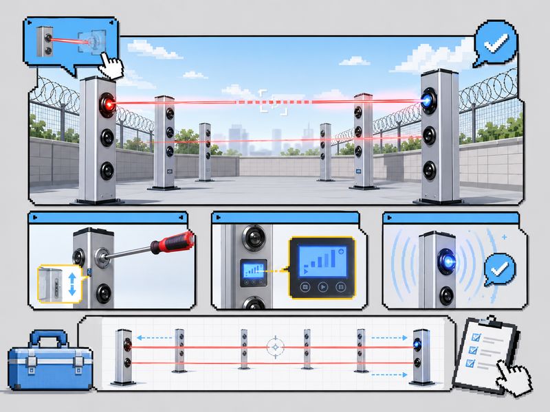
Improve Fiber Cable Installation Quality
Installation quality directly affects monitoring stability. Even the best fiber optic temperature monitoring system may produce false alarms if the sensing cable is installed incorrectly.
Poor installation can create mechanical stress, bending loss, weak signal points, or unstable contact with the monitored object. For example, if a sensing cable is installed too loosely on a power cable, the measured temperature may not accurately reflect the cable surface temperature. If the cable is squeezed or bent sharply, the optical signal quality may degrade.
Good installation practices include:
- Avoid excessive bending and twisting of the fiber cable
- Keep the bending radius within the manufacturer’s recommendations
- Use proper fixing accessories instead of sharp metal fasteners
- Ensure stable contact between the sensing cable and the monitored surface
- Avoid placing cable near irrelevant heat sources
- Protect connectors and splicing points from moisture and dust
- Label zones clearly during installation
- Keep installation records for future maintenance
For power cable temperature monitoring, the sensing fiber should be installed close to the cable surface and fixed at suitable intervals. For pipeline monitoring, the fiber should follow the pipeline route consistently. For fire detection, the fiber should be placed where heat can reach it quickly, but not where harmless heat sources often occur.
Divide Monitoring Areas into Accurate Alarm Zones
Incorrect zone configuration is another common reason for false alarms. If a single alarm zone covers areas with very different thermal environments, the system may struggle to judge what is normal and what is abnormal.
For example, one long fiber route may pass through outdoor areas, underground sections, equipment rooms, tunnel sections, cable trays, and high-temperature operation zones. These areas should not use the same alarm rules.
A better approach is to divide the fiber route into smaller monitoring zones based on environment, asset type, risk level, and operating condition.
| Zone Type | Example Area | Suggested Alarm Strategy |
| Power cable zone | Cable trench, cable tunnel, cable tray | Use temperature rise and differential alarms |
| High-risk fire zone | Conveyor belt, storage area, tunnel | Use rate-of-rise and multi-level alarms |
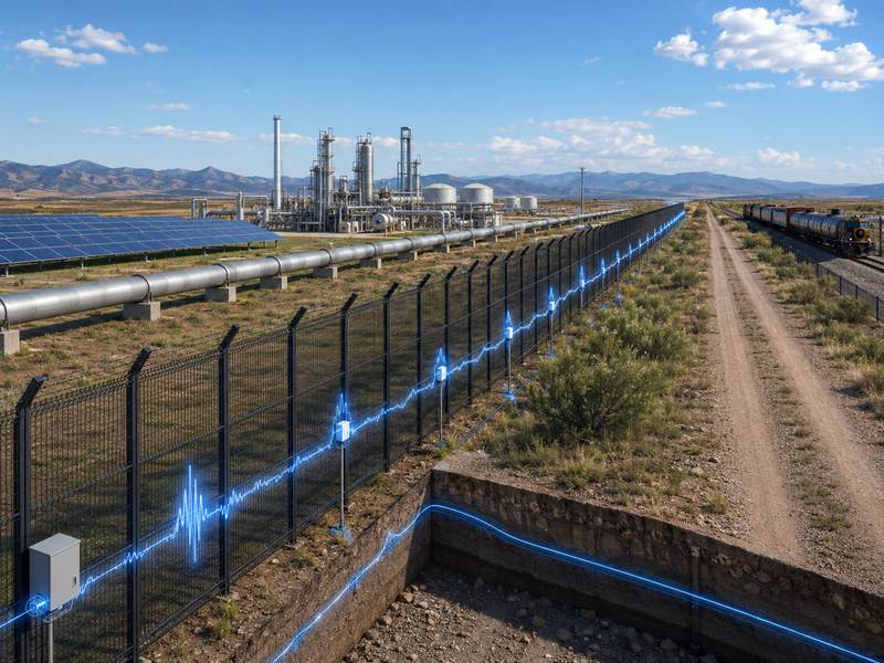
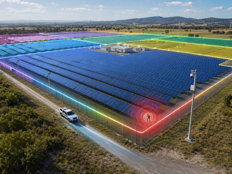
| Outdoor zone | Solar farm, pipeline route, exposed cable | Use environmental compensation |
| Equipment zone | Transformer, motor, switchgear area | Use asset-specific thresholds |
| Transition zone | Indoor-to-outdoor route, ventilation area | Use special baseline settings |
Accurate zone division makes alarm logic more specific and reduces the chance of normal environmental changes triggering unnecessary alarms.
Use Multi-Level Alarm Settings
A single alarm level is often too simple for fiber optic temperature monitoring. If the system only has “normal” and “alarm” states, operators may receive too many urgent alarms. This can lead to alarm fatigue and slower response to real emergencies.
Multi-level alarms provide a better structure. The system can classify events according to severity, giving operators time to evaluate early warnings before a critical alarm occurs.
A typical multi-level alarm design may include:
| Alarm Level | Trigger Condition | Operator Action |
| Notice | Temperature slightly above normal baseline | Record and observe |
| Warning | The temperature continues rising or exceeds the early threshold | Check operating condition |
| Alarm | The temperature exceeds the safety limit, or the rise rate is abnormal | Arrange inspection |
| Critical alarm | Rapid temperature rise or high-risk hot spot | Immediate emergency response |
This method reduces false emergency alarms because not every abnormal reading is treated as a dangerous event. Instead, the system gradually escalates the alarm level based on real temperature behavior.
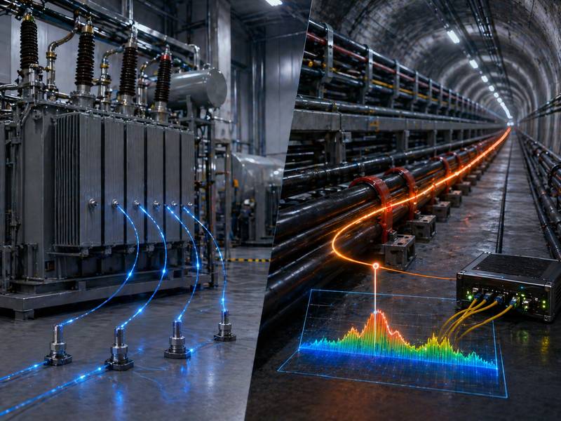
Combine Temperature Data with Other Monitoring Signals
In complex facilities, false alarm reduction can be improved by integrating fiber optic temperature monitoring with other systems. When multiple signals support the same event, alarm reliability becomes much higher.
For example, in a power cable monitoring project, fiber temperature data can be combined with cable load current, ambient temperature, and ventilation status. In a tunnel fire detection project, temperature data can be integrated with smoke detection, video surveillance, or ventilation control systems.
Useful integration data may include:
- Ambient temperature
- Electrical load current
- Equipment operation status
- Smoke or gas detection
- Video monitoring
- Fire alarm system
- SCADA or BMS data
- Weather data for outdoor applications
| Integrated Signal | How It Helps Reduce False Alarms |
| Ambient temperature | Distinguishes environmental heating from real fault |
| Load current | Explains normal cable temperature rise under heavy load |
| Video surveillance | Confirms whether there is visible fire or abnormal activity |
| Smoke detector | Helps verify fire-related alarms |
| Ventilation status | Explains local temperature changes in tunnels or rooms |
| Weather data | Supports outdoor temperature compensation |
Multi-source verification is especially valuable for high-risk environments where both false alarms and missed alarms can be costly.
Optimize Signal Processing and Data Filtering
Fiber optic temperature monitoring systems collect large amounts of data. Without proper signal processing, noise and unstable data points may create false alarms.
Data filtering helps remove abnormal points caused by signal disturbance, connector instability, or temporary measurement errors. However, filtering must be carefully designed. Excessive filtering may delay real alarm detection, while insufficient filtering may allow too many false alarms.
Common signal optimization methods include:
- Moving average filtering
- Abnormal point removal
- Signal strength monitoring
- Temperature smoothing
- Historical baseline comparison
- Spatial comparison between adjacent sensing points
- Automatic compensation for known interference
The goal is not to hide abnormal data, but to identify whether the abnormal data represents a real thermal event.
For example, if only one point shows a sharp temperature jump while nearby points remain completely normal and the signal strength is unstable, the system may classify it as a signal anomaly. If several adjacent points show a continuous temperature rise, the event is more likely to be real.
Maintain Stable Calibration and System Health
Regular calibration and maintenance are important for long-term false alarm reduction. Over time, fiber connectors may become dirty, splicing points may weaken, cables may be damaged, and system parameters may drift.
A good maintenance plan should include routine inspection of both hardware and software settings.
| Maintenance Item | Recommended Check | Purpose |
| Fiber connector | Check cleanliness and connection stability | Prevent signal loss |
| Fiber cable route | Inspect for bending, damage, or loose fixing | Maintain stable sensing |
| Splicing point | Check optical loss and protection status | Avoid weak signal sections |
| Alarm threshold | Review based on seasonal and operational changes | Reduce unnecessary alarms |
| Zone configuration | Confirm route and asset mapping | Improve alarm location accuracy |
| Software records | Analyze alarm history and false alarm patterns | Optimize alarm logic |
| Backup system | Check data storage and communication | Ensure continuous monitoring |
Maintenance should not only focus on repairing faults. It should also include reviewing alarm history. If the same location repeatedly generates false alarms, engineers should check whether the cause is environmental, mechanical, or software-related.
Use AI-Based Alarm Recognition for Complex Sites
For complex monitoring environments, AI-based alarm recognition can further reduce false alarms. Instead of relying only on simple thresholds, AI models can learn normal temperature patterns and identify abnormal events more intelligently.
AI-based systems can analyze historical temperature data, load changes, environmental conditions, event duration, and spatial temperature distribution. This allows the system to separate normal operating conditions from real risks.
Typical AI-based false alarm reduction functions include:
- Automatic recognition of normal thermal patterns
- Identification of repeated false alarm locations
- Event classification by risk level
- Adaptive alarm threshold adjustment
- Correlation analysis with external data
- Prediction of potential overheating trends
AI is not a replacement for good installation and correct system design, but it can significantly improve alarm accuracy when the monitoring environment is complex.
Build a Practical False Alarm Reduction Workflow
Reducing false alarms should be a continuous process. A practical workflow can help project owners, engineers, and operators improve system performance step by step.
| Step | Action | Expected Result |
| 1 | Analyze the application environment | Identify heat sources and risk areas |
| 2 | Design a proper sensing cable route | Improve temperature measurement accuracy |
| 3 | Divide alarm zones | Apply suitable rules for each area |
| 4 | Set dynamic thresholds | Reduce unnecessary alarms |
| 5 | Enable trend analysis | Avoid alarms from short-term fluctuation |
| 6 | Integrate external data | Improve event verification |
| 7 | Review alarm records | Find repeated false alarm causes |
| 8 | Adjust settings regularly | Keep the system accurate over time |
This workflow helps ensure that false alarm reduction is not a one-time setting, but an ongoing optimization process.
Best Practices for Different Applications
Different industries have different false alarm challenges. A power cable system may need load-based temperature compensation, while a tunnel fire detection system may need fast response and strong environmental filtering.
| Application | Common False Alarm Cause | Recommended Solution |
| Power cable monitoring | Load changes and seasonal temperature variation | Use load data and dynamic thresholds |
| Tunnel fire detection | Ventilation, vehicles, and sunlight at entrances | Use zone-based alarm logic |
| Pipeline monitoring | Outdoor temperature changes and uneven insulation | Use environmental compensation |
| Conveyor belt monitoring | Dust, friction heat, and nearby machinery | Use the rate-of-rise and location-based alarm |
| Data center monitoring | Airflow changes and cooling system cycling | Integrate HVAC status |
| Energy storage facility | Local equipment heat and ventilation changes | Use multi-signal verification |
A reliable system should be customized according to the actual application, not configured with one standard threshold for every project.
False alarms in fiber optic temperature monitoring can reduce reliability, raise costs, and weaken user trust. They can be minimized through proper design, quality installation, smart alarm settings, signal optimization, and regular maintenance.
With dynamic thresholds, accurate zoning, trend analysis, multi-level alarms, and AI recognition, the system can detect real risks more accurately and provide more reliable long-term protection.